
BLR-320 · Lesson 4 of 12 · 19 min
Section VIII: pressure vessels
V-412, the knockout drum Kiera helped lay out two winters ago, has been in service at Northgate for more than two years, and its sister, V-414, left the shop in March. Harjit brings the V-412 design calculation package to class and hands out copies with the numbers blacked out. "By the end of tonight," he says, "you'll be able to fill these back in." Section VIII, Division 1 is the code most of Ironbridge's shop work is built to: drums, separators, receivers, exchanger shells and channels. This lesson covers how Division 1 is organized, how shell and head thicknesses are worked out, what joint efficiency and corrosion allowance mean, how openings are reinforced, when welds must be radiographed and heat treated, and how a vessel is pressure tested.
How Division 1 is organized
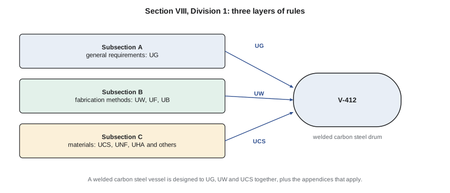
Division 1 is built in three layers. Subsection A, the general requirements in UG paragraphs, applies to every vessel: materials, design for internal and external pressure, openings and reinforcement, fabrication tolerances, inspection, testing, marking and data reports. Subsection B adds requirements for each method of fabrication: UW for welding, UF for forging and UB for brazing. Subsection C adds requirements for each class of material: UCS for carbon and low-alloy steel, UNF for nonferrous metals, UHA for high-alloy steel, UCI for cast iron and others. For a welded carbon steel drum like V-412, the designer works through UG, UW and UCS together, plus the mandatory appendices that apply.
Hoop stress and longitudinal stress
Pressure inside a cylinder pulls the shell in two directions. Around the circumference it creates hoop stress, which tries to split the shell along its length; along the axis it creates longitudinal stress, which tries to pull the shell apart around its girth. For a thin cylinder the hoop stress is twice the longitudinal stress, so a pressurized pipe that fails usually splits along its length. That is also why the longitudinal seams of a shell, which carry the hoop stress, are the more critical welds.
Division 1 turns this into two thickness formulas in UG-27. The one for hoop stress governs almost every shell; the one for longitudinal stress is checked as well, because it can govern where the circumferential seams have a low joint efficiency or extra loads act on the vessel.
In both, t is the minimum required thickness, P the design pressure, R the inside radius, S the allowable stress of the material at the design temperature from Section II, Part D, and E the joint efficiency of the weld that carries the stress. The small terms with P correct the simple thin-wall result for the thickness of the shell.
Joint efficiency and radiography
A welded seam is treated as weaker than solid plate unless it has been examined well enough to show otherwise. Joint efficiency, E, is the factor that does this. A double-welded butt joint that has been fully radiographed gets an efficiency of 1.0; the same joint spot radiographed gets 0.85; and if it is not radiographed at all it gets 0.70. A lower efficiency means a thicker shell for the same pressure, so the designer chooses between paying for more radiography and paying for more steel. Paragraph UW-12 sets the efficiencies, and UW-11 says which joints must be fully radiographed regardless, for example in lethal service, in some thick sections and in some unfired steam boilers.
| Type of joint | Full radiography | Spot radiography | No radiography |
|---|---|---|---|
| Double-welded butt, or equivalent | 1.00 | 0.85 | 0.70 |
| Single-welded butt with backing strip left in | 0.90 | 0.80 | 0.65 |
| Single-welded butt without backing | Not used | Not used | 0.60 |
The radiography decision shows up on the nameplate and data report as a marking such as RT 1 for a vessel fully radiographed, or RT 2, RT 3 or RT 4 for lesser degrees. For the boilermaker it shows up on the weld map, which tells the fitter and welder which seams will be shot and therefore which ones have no room for a careless root.
Corrosion allowance and design conditions
Most vessels lose metal in service. The designer adds a corrosion allowance to the required thickness so that the vessel still has enough steel at the end of its planned life. The allowance is set by the owner from experience with the process, typically a few millimetres for carbon steel in mildly corrosive service, and it is added to whichever pressure thickness governs.
A vessel also has a design pressure and a design temperature, chosen by the process engineer above the highest the vessel will see in operation; a minimum design metal temperature, the coldest the steel may be while pressurized, which decides whether impact testing is needed; and a maximum allowable working pressure, which is the highest pressure the finished vessel can take at its design temperature, calculated from the actual thicknesses used. The MAWP is often a little higher than the design pressure, because plate comes in standard thicknesses, and it is the MAWP that goes on the nameplate.
Worked problem
Filling in V-412's shell calculation
V-412 has an inside diameter of 1,800 mm (72 in), so an inside radius of 900 mm (36 in). Its design pressure is 1,700 kPa (250 psi), the allowable stress is taken as 138,000 kPa (20,000 psi), the long seams are fully radiographed, so E = 1.0, and the corrosion allowance is 3 mm (1/8 in). What thickness is required, and what is the MAWP with the 16 mm (5/8 in) plate actually used?
Show solution
- Hoop formula: t = PR / (SE − 0.6P).
- Longitudinal formula: t = PR / (2SE + 0.4P); the larger governs.
- Add the corrosion allowance and compare with the plate used.
- For the MAWP, work the formula backwards with the corroded thickness and the corroded radius.
Answer: The hoop formula governs; with the corrosion allowance the required thickness is about 14.2 mm (0.58 in), so 16 mm (5/8 in) plate is enough, and the MAWP in the corroded condition comes out a little above the design pressure.
# V-412 shell: required thickness, MAWP and test pressure (metric, illustrative stresses)
P, R, S, E, CA = 1700, 900, 138000, 1.0, 3     # design pressure, inside radius, allowable stress, joint efficiency, corrosion allowance
t_circ = P * R / (S * E - 0.6 * P)         # thickness for hoop stress (longitudinal seams)
t_long = P * R / (2 * S * E + 0.4 * P)     # thickness for longitudinal stress (circumferential seams)
t_req = max(t_circ, t_long) + CA
print(f"hoop: {t_circ:.1f} mm  longitudinal: {t_long:.1f} mm  required with corrosion allowance: {t_req:.1f} mm")
t = 16                                     # nominal plate thickness used
tc, Rc = t - CA, R + CA                     # corroded condition
mawp = S * E * tc / (Rc + 0.6 * tc)
print(f"plate {t} mm: MAWP in the corroded condition about {mawp:,.0f} kPa")
stamped = 1700
lsr = 1.0                                   # ratio of allowable stresses, test to design temperature (taken as 1 here)
print(f"stamped MAWP {stamped:,} kPa: hydrostatic test at least 1.3 x {stamped:,} x {lsr} = {1.3 * stamped * lsr:,.0f} kPa")
print(f"examination after the hold at test pressure / 1.3 = {1.3 * stamped / 1.3:,.0f} kPa")hoop: 11.2 mm longitudinal: 5.5 mm required with corrosion allowance: 14.2 mm plate 16 mm: MAWP in the corroded condition about 1,970 kPa stamped MAWP 1,700 kPa: hydrostatic test at least 1.3 x 1,700 x 1.0 = 2,210 kPa examination after the hold at test pressure / 1.3 = 1,700 kPa
Heads and openings
Heads have their own formulas in UG-32: an ellipsoidal head of the common 2:1 shape needs about the same thickness as a shell of the same diameter, a hemispherical head about half, and a flanged and dished head somewhat more. BLR-310 covered the shapes; here the point is that the head maker supplies a head whose minimum thickness after forming meets the formula, because forming thins the plate, especially in the knuckle. The receiving inspection checks that minimum before the head is fitted.
Every opening cut in a shell or head removes metal that was carrying stress. Division 1 requires that the metal removed be replaced, within a zone around the opening, by extra thickness in the shell, the nozzle neck or a reinforcing pad. The calculation, in paragraphs UG-37 to UG-45, compares the area removed with the areas available. A reinforcing pad has a small tapped telltale hole so that a leak through the nozzle weld shows during the test instead of hiding under the pad. When the shop is asked to move a nozzle or change its size, the reinforcement must be rechecked by the designer, because a nozzle that is too close to a seam or to another nozzle may no longer have enough metal around it.
Heat treatment and impact testing
Carbon steel parts above a certain thickness must be given post-weld heat treatment, under the rules of UCS-56, to relieve the residual stresses of welding and to temper hard zones. For carbon steel the trigger is a nominal thickness above 38 mm (1 1/2 in), or above 32 mm (1 1/4 in) unless preheat is applied, with other triggers for particular services and materials. Heat treatment can also be required by the owner's specification, for example in caustic or wet sour service, even where the code would not require it.
At low temperatures, carbon steel can fail by brittle fracture, cracking suddenly at a stress far below its strength. Division 1 controls this with impact test exemption curves in UCS-66: for a given material group and thickness, the curve gives the coldest temperature at which the steel may be used without impact tests. Below that, the plate, the welds and the heat-affected zones must be impact tested. Northgate's winter start-ups are why V-412's minimum design metal temperature is low, and why its plate and welding procedure were impact tested.
Pressure testing
Every Division 1 vessel is pressure tested before it goes into service. The standard test is hydrostatic, under UG-99, at not less than 1.3 times the MAWP multiplied by the lowest ratio of the allowable stress at test temperature to the allowable stress at design temperature. After the test pressure has been held, it is reduced, and the inspector examines the vessel at a pressure not less than the test pressure divided by 1.3. A pneumatic test, under UG-100, is allowed only where a hydrostatic test is not practicable, at a lower ratio of 1.1, and with far stricter precautions, because of the energy stored in compressed gas.
The test is witnessed by the inspector, the gauges are calibrated and of a suitable range, the test water is at a temperature that keeps the metal well above the risk of brittle fracture, and the vessel is vented while filling so that air is not trapped. The test is recorded with the date, the pressure, the duration, the water temperature, the gauges used and the inspector's acceptance, and it appears on the data report.
Nozzle loads and supports
A vessel is not only loaded by its own pressure. Piping pulls and pushes on its nozzles, wind and earthquakes act on tall columns, the weight of the contents and the vessel itself bear on its saddles or skirt, and hot vessels grow as they heat up. Division 1 requires the designer to consider these loads, but it gives fewer formulas for them than for pressure, so designers use methods from other standards and from engineering practice. For the boilermaker the practical point is that supports, saddles, skirts and lugs are part of the design. A saddle that is moved, a clip added to the shell or a lug cut off to clear a pipe changes the loads, and the designer must agree before anyone changes them.
Attachments welded to the shell, even small ones such as insulation clips or ladder brackets, are welded under the vessel's welding procedures and are shown on the drawings, because a fillet weld on a pressure part can be the start of a crack if it is poorly made, and on heat-treated vessels it must be done before heat treatment.
Common mistakes
MistakeThinking the circumferential seams are the most critical welds on a shell.
InsteadHoop stress is twice the longitudinal stress, so the long seams carry the higher stress.
MistakeUsing the design pressure as the nameplate pressure.
InsteadThe nameplate carries the MAWP, calculated from the thicknesses actually used.
MistakeMoving a nozzle a little to suit fit-up.
InsteadAny change to an opening needs the designer to recheck reinforcement and spacing.
MistakePlugging a reinforcing pad's telltale hole before the test.
InsteadThe telltale shows a leak at the nozzle weld; it stays open during the test.
Summary and key terms
- Section VIII, Division 1 has general rules (UG), fabrication rules (UW, UF, UB) and material rules (UCS, UHA and others).
- Hoop stress governs most shells; UG-27 gives formulas for both directions.
- Joint efficiency depends on joint type and radiography, from 1.0 down to 0.60 or less.
- Corrosion allowance is added to the pressure thickness; the MAWP is calculated from the thicknesses used.
- Openings must be reinforced, and heat treatment and impact testing depend on material, thickness and temperature.
- The standard test is hydrostatic at 1.3 times the MAWP times the stress ratio, examined at test pressure divided by 1.3.
- Hoop stress
- Stress around the circumference of a cylinder, about twice the longitudinal stress.
- Joint efficiency
- A factor that reduces the allowable stress at a weld according to its type and the extent of radiography.
- Corrosion allowance
- Extra thickness added to allow for metal loss in service.
- MDMT
- Minimum design metal temperature: the coldest the steel may be while pressurized.
- Reinforcement
- Extra metal around an opening that replaces the metal removed.
- Telltale hole
- A small hole in a reinforcing pad that shows a leak during testing.
Practice problems
Work each problem on paper first, then reveal the answer to check.
Why does a pressurized pipe usually split along its length?
Show answer
Because hoop stress, which acts around the circumference, is about twice the longitudinal stress.
A double-welded butt seam is spot radiographed. What joint efficiency applies?
Show answer
0.85.
A vessel has an MAWP of 2,000 kPa (290 psi) and a stress ratio of 1.0. What is the minimum hydrostatic test pressure?
Show answer
1.3 × 2,000 = 2,600 kPa.
At what pressure is a vessel examined after the hold at test pressure?
Show answer
At not less than the test pressure divided by 1.3.
Lesson quiz · 5 questions
Score 60% or more to complete this lesson.
Create a free account to save your progress, take quizzes and earn a certificate.