
AERO-220 · Lesson 11 of 12 · 22 min
Turning flight and the V-n diagram
Every aircraft turns, and every turn puts extra load on the wing. A gentle airliner turn barely registers with the passengers, but a steep turn in a holding pattern, a pull-up to avoid terrain, or a strong gust in turbulent air can load the structure to a large multiple of its weight. This lesson treats turning flight as a performance problem, finding the radius and rate of turn, then shows how the same load factor idea defines the flight envelope that the structure must be designed for: the V-n diagram. For the Tern, these numbers decide how tightly it can manoeuvre around the terrain near some northern strips and how much margin its wing has in the rough air common over the prairies in summer.
Load factor in a level turn
In a level, coordinated turn, the aircraft banks so that the lift vector tilts toward the centre of the turn. The vertical component of lift must still balance the weight, and the horizontal component provides the centripetal force. The ratio of lift to weight is the load factor \(n\), and the bank angle \(\phi\) alone sets it.
At 30 degrees of bank, the load factor is 1.15; at 45 degrees, 1.41; at 60 degrees, 2.0. That last figure means every part of the aircraft, and every passenger, feels twice their normal weight. Since lift must rise by the load factor, the stall speed rises by its square root: in a 60 degree bank the stall speed is 41 percent higher than in level flight. Many stall accidents happen in turns at low altitude for exactly this reason, often when a pilot tightens a turn near the ground.
The radius depends on speed squared and on bank angle, so tight turns need low speed and steep bank. The rate of turn rises with load factor and falls with speed. Instrument flying uses a standard-rate turn of 3 degrees per second, which completes a full circle in two minutes; a handy rule of thumb gives the bank angle needed as about the true airspeed in knots divided by 10, plus 7. Large, fast aircraft often fly half-standard-rate turns to keep the bank angle within the 25 to 30 degrees that passengers accept comfortably.
# Turning flight and the V-n diagram for the Tern
import math
g, S, m, AR = 9.81, 28.0, 6500.0, 10.3
W = m * g; WS = W / S
c = math.sqrt(S / AR)                               # mean chord, m
rho0 = 1.225
def rho_at(h):
    T = 288.15 - 0.0065 * h
    return 101325 * (T / 288.15) ** 5.2559 / (287.05 * T)
# 1. Level turns: load factor, radius and rate for several bank angles at 300 km/h true airspeed
V = 300 / 3.6
print("Bank   n     radius   rate")
for phi in (15, 30, 45, 60):
    n = 1 / math.cos(math.radians(phi))
    R = V**2 / (g * math.tan(math.radians(phi)))
    print(f"{phi:3d}°  {n:4.2f}  {R:6.0f} m  {math.degrees(V / R):4.1f} °/s")
phi_std = math.degrees(math.atan(math.radians(3) * V / g))
print(f"Standard-rate turn (3 °/s) at 300 km/h needs {phi_std:.1f}° of bank")
# 2. Sustained turn at 3000 m on generator power (665 kW shaft, propeller efficiency 0.82)
rho = rho_at(3000); Pa = 0.82 * 665e3
best = (None, 0)
for v in range(200, 380, 5):
    V = v / 3.6; q = 0.5 * rho * V**2
    n_power = math.sqrt(max(0.0, (Pa / V - q * S * 0.028) / (q * S * 0.039)) ) * q * S / W   # thrust = drag
    n_stall = q * S * 1.6 / W
    n = min(n_power, n_stall, 3.0)
    if n > 1:
        R = V**2 / (g * math.sqrt(n * n - 1))
        if best[0] is None or R < best[0][1]: best = ((v, R, n), R)
v, R, n = best[0]
print(f"Tightest sustained level turn at 3000 m: {v} km/h, n = {n:.2f}, bank {math.degrees(math.acos(1/n)):.0f}°, radius {R:.0f} m")
# 3. V-n diagram: manoeuvre envelope and gust lines (speeds as equivalent airspeed)
n_pos = min(3.8, 2.1 + 24000 / (m / 0.4536 + 10000))   # traditional normal-category formula, weight in lb
n_neg = -0.4 * n_pos
Vs1 = math.sqrt(2 * WS / (rho0 * 1.6)); Vs_neg = math.sqrt(2 * WS / (rho0 * 0.8))
VA = Vs1 * math.sqrt(n_pos)
VC, VD = 330 / 3.6, 415 / 3.6
a = 2 * math.pi * AR / (AR + 2)                          # lift-curve slope, per radian
mu_g = 2 * WS / (rho0 * c * a * g); Kg = 0.88 * mu_g / (5.3 + mu_g)
def gust(U, V): return 1 + rho0 * Kg * U * V * a / (2 * WS)
print(f"Limit load factors: +{n_pos:.2f}, {n_neg:.2f}")
print(f"V_S1 {Vs1*3.6:.0f} km/h, V_A {VA*3.6:.0f} km/h, V_C {VC*3.6:.0f} km/h, V_D {VD*3.6:.0f} km/h (EAS)")
print(f"Gust alleviation factor Kg = {Kg:.2f}, lift-curve slope {a:.2f} per radian")
print(f"Gust load factor at V_C, 15.24 m/s (50 ft/s): {gust(15.24, VC):.2f}; at V_D, 7.62 m/s (25 ft/s): {gust(7.62, VD):.2f}")
print(f"Negative gust at V_C: {2 - gust(15.24, VC):.2f}")Bank n radius rate 15° 1.04 2642 m 1.8 °/s 30° 1.15 1226 m 3.9 °/s 45° 1.41 708 m 6.7 °/s 60° 2.00 409 m 11.7 °/s Standard-rate turn (3 °/s) at 300 km/h needs 24.0° of bank Tightest sustained level turn at 3000 m: 250 km/h, n = 1.54, bank 50°, radius 420 m Limit load factors: +3.09, -1.23 V_S1 174 km/h, V_A 305 km/h, V_C 330 km/h, V_D 415 km/h (EAS) Gust alleviation factor Kg = 0.78, lift-curve slope 5.26 per radian Gust load factor at V_C, 15.24 m/s (50 ft/s): 2.55; at V_D, 7.62 m/s (25 ft/s): 1.98 Negative gust at V_C: -0.55
Limits on turning
The program shows three limits on how tightly the Tern can turn. The first is aerodynamic: the wing cannot produce more than \(C_{L,max}\) times the dynamic pressure, so at low speed the load factor is capped by \(n = q S C_{L,max}/W\). The second is structural: above a certain speed, the wing could produce more lift than the structure is designed to carry. The third is power: a turn at load factor \(n\) needs \(n\) times the lift, and the induced drag grows with \(n^2\), so a sustained turn without losing height or speed needs more thrust than level flight. The tightest turn the Tern can sustain at 3000 m on its generator alone is at about 250 km/h, with a load factor of 1.54 and a bank of about 50 degrees, giving a radius of about 420 m. Tighter turns are possible, but only by trading height or speed for the missing power.
Worked problem
A turn in a valley
Approaching a strip in a valley at 250 km/h, a pilot needs to reverse course within a valley 1.2 km wide. Find the minimum bank angle required for a 180 degree level turn that fits within the valley with a 200 m margin each side, and the stall speed in that turn if the level-flight stall speed with approach flaps is 150 km/h.
Show solution
- Available diameter: \(1200 - 2\times 200 = 800\ \text{m}\), so \(R = 400\ \text{m}\).
- \(V = 250/3.6 = 69.4\ \text{m/s}\); \(\tan\phi = V^2/(gR) = 4823/(9.81\times 400) = 1.23\), so \(\phi = 51^\circ\).
- Load factor: \(n = 1/\cos 51^\circ = 1.59\).
- Stall speed in the turn: \(150\sqrt{1.59} = 189\ \text{km/h}\).
Answer: A 51 degree bank turn at 250 km/h leaves a margin of about 61 km/h above the stall, adequate but not generous, and requires more power than the generator alone can supply at that speed. Slowing to 220 km/h first would allow a 44 degree bank for the same radius. Route planners for mountainous strips build such checks into the published approach and missed-approach procedures, so that pilots never need steep turns close to terrain.
The V-n diagram
The V-n diagram plots the load factors the aircraft can experience against its equivalent airspeed, and it defines the envelope within which the structure must not deform permanently. Airworthiness standards define the boundaries. At low speed, the curved lines are the stall limits, \(n = \rho_0 V_E^2 S C_{L,max}/(2W)\) for positive load factors and the corresponding negative-lift limit below. Horizontal lines at the positive and negative limit load factors cap the envelope, and a vertical line at the design dive speed \(V_D\) closes it on the right.
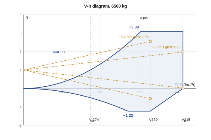
The traditional limit load factors for normal-category aeroplanes, retained in the consensus standards that support today's the airworthiness standards Transport Canada applies to commuter aeroplanes (Chapter 523 of the Airworthiness Manual), come from a formula in the aircraft's weight. The positive limit may not be less than \(2.1 + 24000/(W + 10000)\) with \(W\) in pounds, though it need not exceed 3.8; the negative limit is 0.4 times the positive value. For the Tern at 14,330 lb, that gives +3.09 and −1.23. Utility and aerobatic categories use higher fixed values. The structure must carry the limit loads without permanent deformation and must carry 1.5 times the limit loads, the ultimate loads, without failure for at least a few seconds.
| Speed | Meaning | Tern value (EAS) |
|---|---|---|
| V_S1 | Stall speed, clean, at the weight considered | 174 km/h |
| V_A | Design manoeuvring speed, V_S1 √n | 305 km/h |
| V_C | Design cruising speed | 330 km/h |
| V_D | Design dive speed, at least 1.25 V_C | 415 km/h |
| V_NE / V_MO | Never-exceed or maximum operating speed, below V_D | Set from V_D with a margin |
The design manoeuvring speed \(V_A\) is where the positive stall line meets the limit load factor. Below \(V_A\), the wing stalls before it can overload the structure, so a full, abrupt pull on the controls cannot exceed the limit load. Above it, it can. Pilots slow toward \(V_A\), or the related turbulence penetration speed, in severe turbulence for this reason. Because \(V_A\) scales with the square root of weight, it is lower at light weights, a point that surprises many pilots. One caution matters: \(V_A\) protects against a single full deflection in one axis, not against repeated or reversing control inputs, which can overload the tail or fin even below \(V_A\).
Gust loads
Atmospheric turbulence can load the structure as severely as any manoeuvre. A vertical gust of velocity \(U\) changes the wing's angle of attack by about \(U/V\), which changes the lift coefficient by \(a\,U/V\), where \(a\) is the lift-curve slope. The resulting change in load factor rises with speed and falls with wing loading. Real gusts build up over a distance, and the aircraft responds by moving up with the gust, so design rules apply a gust alleviation factor \(K_g\) that depends on the aircraft's mass ratio.
The traditional rules require the structure to withstand derived gusts of 50 ft/s at the design cruising speed and 25 ft/s at the design dive speed, at altitudes up to 20,000 ft, with smaller gusts higher up; commuter-category aircraft add a larger gust at the rough-air speed. Plotting the gust load factors as straight lines from \(n = 1\) at zero speed gives the gust envelope. For the Tern, the 50 ft/s gust at \(V_C\) gives a load factor of 2.55 and the 25 ft/s gust at \(V_D\) gives 1.98, both inside the manoeuvre envelope, so manoeuvres set the design loads at maximum weight.
Gust loads are more severe at light weight, because the wing loading in the denominator falls. A lightly loaded Tern flying fast through turbulence at the end of a long flight experiences larger load-factor excursions than a heavy one, and the structural engineers must check the envelope at several weights and altitudes. Aircraft with low wing loadings, such as light sport aircraft and the Skiff cargo drone, are particularly sensitive: the Skiff's gust lines may cross outside its manoeuvre envelope, which then sets its design loads.
Common mistakes
MistakeThinking load factor depends on speed in a level turn.
InsteadIn a level coordinated turn, load factor depends only on bank angle: n = 1/cos φ.
MistakeTreating V_A as a speed below which any control input is safe.
InsteadV_A protects against one full deflection in one axis, not repeated or reversing inputs.
MistakeAssuming V_A is fixed for an aircraft.
InsteadV_A falls with the square root of weight, so it is lower when the aircraft is light.
MistakeAssuming gusts are less important than manoeuvres.
InsteadFor light or lightly loaded aircraft, gust loads can exceed manoeuvre loads.
MistakeConfusing limit and ultimate loads.
InsteadLimit loads are the largest expected in service; ultimate loads are 1.5 times limit loads and must not cause failure.
Summary and key terms
- In a level turn, n = 1/cos φ, R = V²/(g tan φ) and turn rate ω = g√(n² − 1)/V.
- Stall speed in a turn rises with the square root of load factor.
- Turns are limited by C_L,max, structural load factor and available power.
- The V-n diagram bounds load factor against equivalent airspeed between stall lines, limit load factors and V_D.
- V_A is where the stall line meets the positive limit load factor.
- Gust load factors rise with speed and fall with wing loading, and are reduced by K_g.
- Load factor
- The ratio of lift to weight, n = L/W.
- Standard-rate turn
- A turn at 3 degrees per second, completing 360 degrees in two minutes.
- V-n diagram
- A plot of the load factors an aircraft must withstand against equivalent airspeed.
- Limit load factor
- The largest load factor expected in service, which the structure must carry without permanent deformation.
- Ultimate load
- The limit load multiplied by a factor of safety of 1.5, which the structure must carry without failure.
- Design manoeuvring speed
- V_A, the speed at which the stall line meets the positive limit load factor.
- Gust alleviation factor
- K_g, a factor that reduces the sharp-edged gust load to account for gust build-up and aircraft response.
Practice problems
Work each problem on paper first, then reveal the answer to check.
Find the load factor and the stall speed in a 40 degree bank turn if the level stall speed is 150 km/h.
Show answer
n = 1/cos 40° = 1.31; stall speed 150 × √1.31 = 172 km/h.
Find the radius of a 30 degree bank turn at 200 km/h.
Show answer
V = 55.6 m/s; R = 55.6²/(9.81 × tan 30°) = 545 m.
Using the rule of thumb, estimate the bank angle for a standard-rate turn at 160 kt.
Show answer
160/10 + 7 = 23 degrees.
Find the positive and negative limit load factors for a normal-category aeroplane of 12,000 lb.
Show answer
2.1 + 24000/22000 = 3.19; negative 1.28.
An aircraft's V_A is 300 km/h at 6500 kg. Find V_A at 5000 kg.
Show answer
300 × √(5000/6500) = 263 km/h.
In the program, reduce the mass to 5000 kg. What happens to the gust load factor at V_C?
Show answer
It rises to about 2.95, close to the limit load factor, because the wing loading is lower.
Lesson quiz · 5 questions
Score 60% or more to complete this lesson.
Create a free account to save your progress, take quizzes and earn a certificate.