
PWR-510 · Lesson 4 of 12 · 27 min
Plant layout and piping design
▶ Video coming soon A video version of this lesson is on the way.
Keswold's steam reaches Marrowby Foods through a single NPS 8 line that leaves the extraction header, climbs onto a pipe bridge, crosses the road and drops into Marrowby's boiler room about 500 ft away, with an NPS 3 condensate return line beside it. Anselm had walked the bridge hundreds of times. For the expansion study, Morwenna asked him to walk it again with a different question: where would a second line go, how would it move as it heated, and how would a new pair of standby boilers fit into Keswold's site without blocking the gas turbine's maintenance laydown area?
Layout and piping are where design decisions become permanent. A pump can be replaced in a day; a building in the wrong place, a pipe rack with no spare space or a steam line that cannot drain will trouble a plant for its whole life. This lesson covers the principles of plant layout, the codes for power piping, the sizing of steam lines, thermal expansion and flexibility, supports, drainage and water hammer, and the drawings and reviews that turn a layout into something that can be built and operated.
Principles of plant layout
A good layout follows the process, keeps hazards apart, and leaves room to operate, maintain and expand. The main considerations are the same whether the project is a whole plant or a pair of boilers added to an existing one.
- Process flow: equipment is arranged in the order the steam, water and fuel move through it, with short, direct runs for large and hot lines.
- Maintenance access: every item needs a way in and a way out. Turbine rotors, gas turbine modules, boiler tubes, pump rotating assemblies and heat exchanger bundles need pull space, crane coverage or a clear path for a mobile crane, and a laydown area.
- Operating access: valves, instruments and sample points the operators use often must be reachable from a floor or platform, not from a ladder.
- Safety separation: fuel systems, transformers, chemical storage and hazardous areas are separated from ignition sources, control rooms and escape routes, with spill containment and fire protection.
- Egress: two ways out of every room and platform where people work, kept clear.
- Future expansion: space on pipe racks, in electrical rooms and on the site for the next project.
- Neighbors and environment: noise, plume visibility, stack location relative to buildings and air intakes, traffic and drainage.
Keswold's site plan, drawn when the plant was designed, shows a reserved area north of the HRSG marked for a future auxiliary boiler, with a space on the pipe rack and a spare breaker in the medium voltage switchgear. Morwenna said that this was the most valuable line on the drawing. "Somebody thought about the next project before they finished the first one. Most plants don't, and then the expansion costs twice as much."
Power piping codes
Boiler external piping, from the boiler to the first stop valves, falls under ASME Section I, and its design and construction follow ASME B31.1, the power piping code, whose current edition is B31.1-2024. Power piping beyond the boiler external piping, such as main steam, feedwater and extraction lines, is also designed to B31.1, while process plant piping is usually designed to B31.3. Ohio's boiler rules cover boiler external piping, and the owner's insurer, its specifications and local codes generally govern the rest (PWR-340).
B31.1 sets rules for materials, design pressure and temperature, wall thickness, flexibility and stress analysis, supports, fabrication, welding, examination and testing, and it requires an operating and maintenance program for covered piping that includes condition assessment of high-energy lines. The code's formulas and allowable stresses govern; the teaching relations in this lesson explain what the code checks.
Sizing a steam line
Steam lines are sized to keep velocity within limits that control pressure drop, noise, erosion and water hammer. Typical design velocities are about 5,000 to 8,000 ft/min for superheated steam in process mains and lower for saturated steam and for long distribution lines (typical; each designer and owner sets its own). The volume flow is the mass flow times the specific volume at the line conditions, and the velocity is the volume flow divided by the inside area of the pipe.
Worked problem
Is the existing line big enough?
Marrowby's design peak after the expansion would be 68,000 lb/h at 175 psia and about 551 °F, where the specific volume is 3.328 ft³/lb (IAPWS-IF97). Find the velocity in NPS 8, NPS 10 and NPS 12 Schedule 40 pipe, with inside diameters of 7.981, 10.020 and 11.938 in.
Show solution
- \[\dot V = \frac{68{,}000 \times 3.328}{60} = 3{,}772 \text{ ft}^3/\text{min}\]
- \[V_8 = \frac{3{,}772}{\pi (7.981/12)^2/4} = 10{,}860 \text{ ft/min} \quad V_{10} = 6{,}890 \text{ ft/min} \quad V_{12} = 4{,}850 \text{ ft/min}\]
Answer: The existing NPS 8 line would run at about 10,900 ft/min at the new peak, well above the usual range, with a large pressure drop and noise. Today, at 48,000 lb/h, it runs at about 7,700 ft/min. A new NPS 10 line sized for the whole peak would run at about 6,900 ft/min, and an NPS 12 line at about 4,900 ft/min with room for further growth. The options are to replace the line with NPS 10 or 12, or to add a second line and run the two in parallel, which also gives Marrowby a spare route when one line is being repaired.
Velocity is a first check. The designer also calculates the pressure drop along the line, including fittings and valves, to confirm that Marrowby still receives steam at the pressure its processes need when the extraction is at its controlled pressure, and checks the line's wall thickness for the design pressure and temperature with the code formula (lesson 2).
Thermal expansion and flexibility
A steel pipe grows as it heats, by its length times its coefficient of expansion times the temperature rise. A long, hot line grows by a surprising amount, and if it is held rigidly between two points, the growth turns into enormous forces on the anchors and the equipment nozzles and into stresses that can crack the pipe or its welds. Piping is therefore designed to be flexible: bends, offsets and loops let the pipe absorb its growth by bending a little, and the code checks that the resulting displacement stress range stays within its allowable range over the life of the line.
Worked problem
How much does the line grow?
The steam line from the extraction header to Marrowby is about 500 ft long, installed at about 50 °F, and runs at about 551 °F. Take the mean coefficient of expansion of carbon steel over this range as 7.2 × 10⁻⁶ per °F (typical). How much does the line grow?
Show solution
- \[\Delta L = 7.2 \times 10^{-6} \times 500 \times 12 \times (551 - 50) = 21.6 \text{ in}\]
Answer: Almost two feet. Held between anchors at each end with no flexibility, the line would push on the extraction header and Marrowby's header with forces that no nozzle could take. The line is therefore divided by anchors into sections, and each section's growth is taken up by an expansion loop or an offset between anchors.
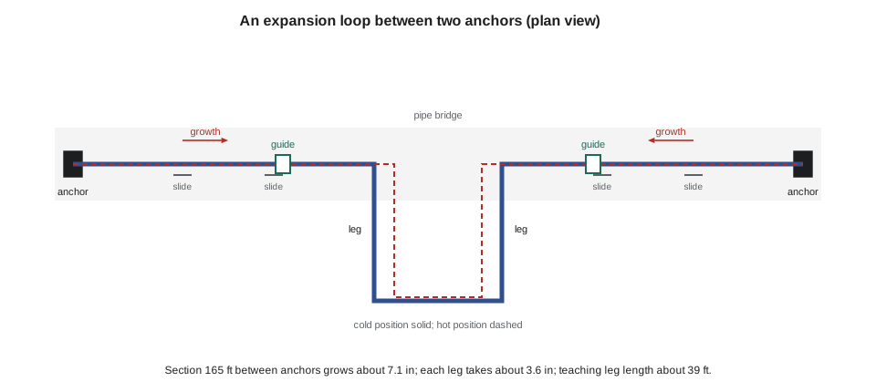
An anchor fixes the pipe in all directions; a guide lets it slide along its axis but not sideways; a sliding support carries its weight while letting it move. Between two anchors, the pipe grows toward a loop, which bends to absorb the growth. A teaching relation for the length of leg needed to take a sideways deflection, from the guided cantilever, shows how the required leg grows with the pipe diameter and the deflection and falls with the allowable stress. Real loops are designed with stress analysis software to the code, with the actual supports, fittings and stress intensification at bends.
Worked problem
A rough loop size
Suppose anchors divide the new NPS 10 line (outside diameter 10.75 in) into sections of 165 ft, each growing about 7.1 in, with a loop in the middle of each section so that each leg of the loop takes about 3.6 in. With E = 29,000,000 psi and a teaching allowable stress range of 15,000 psi, estimate the leg length.
Show solution
- \[L \approx \sqrt{\frac{3 \times 29{,}000{,}000 \times 10.75 \times 3.57}{15{,}000}} = 472 \text{ in} \approx 39 \text{ ft}\]
Answer: About 39 ft, which is why the loops on long steam lines are so large and why pipe bridges are often wider where the loops sit. The estimate is conservative; a stress analysis with the real geometry usually allows smaller loops. The alternative, an expansion joint, takes the movement in a bellows, but bellows need careful guiding and anchoring, can fail suddenly if they are overstressed or corroded, and are a maintenance item; many owners avoid them on high-energy steam.
Supports and hangers
Supports carry the weight of the pipe, its insulation and its contents, and control where it moves. Rigid supports and rod hangers carry weight where the pipe does not move much vertically. Where the pipe rises or falls as it heats, variable spring hangers carry the load through a spring whose force changes a little with movement, and constant support hangers use a spring and lever mechanism to carry nearly the same load over a large movement, for example at a turbine connection. Each spring hanger has a cold and a hot position marked on its scale.
Hangers are one of the most neglected items in power plants. A hanger that has bottomed out, been left with its travel stops in, or been adjusted by someone who did not understand it can shift load onto a turbine nozzle or overstress a weld. Good practice, which B31.1 asks for on covered piping, is to record hanger positions hot and cold at regular intervals, investigate any that are outside their range, and include hangers in the walk-downs after outages. Keswold's hanger survey is part of each outage's checklist, and Ingeborg showed Anselm the record from October: two hangers on the main steam line had readings outside their hot range and were adjusted after an engineering review.
Drainage, warm-up and water hammer
Steam lines must drain. Condensate forms whenever steam meets a surface cooler than itself, most of all during warm-up, and if it collects, steam flowing over it can pick up a slug of water and drive it along the pipe at high speed. When the slug hits a bend, a valve or a closed end, the impact, water hammer, can bend supports, crack fittings and burst valves. The same can happen when steam is admitted to a line full of cold condensate, which flashes and collapses violently.
- Lines slope in the direction of flow, typically about 1/2 in per 10 ft or more (typical).
- Drip legs at low points, before risers, at the ends of mains and at intervals along long runs collect condensate, each with a steam trap and a blowdown valve.
- Warm-up is slow and controlled, with drains open, using a small warm-up bypass around the main isolating valve.
- Isolating valves are opened slowly, and lines that have been shut down are drained before steam is admitted.
Worked problem
How much condensate does a warm-up make?
Estimate the condensate formed when 500 ft of NPS 10 Schedule 40 pipe (40.48 lb/ft) is warmed from 50 °F to 551 °F by steam at 175 psia, where the latent heat is 853 Btu/lb. Take the specific heat of steel as 0.117 Btu/lb·°F and ignore heat lost through the insulation during the warm-up.
Show solution
- \[m_{pipe} = 500 \times 40.48 = 20{,}240 \text{ lb}\]
- \[Q = 20{,}240 \times 0.117 \times 501 = 1.19 \times 10^6 \text{ Btu} \qquad m_c = \frac{1.19 \times 10^6}{853} = 1{,}390 \text{ lb}\]
Answer: About 1,390 lb of condensate, most of it in the first part of the warm-up when the pipe is coldest. If the warm-up took an hour, the drip legs and traps would have to pass about 1,390 lb/h at first, far more than in normal running. That is why warm-up drains are sized for start-up, often with manual bypasses, and why the warm-up rate is limited.
Valves, isolation and maintainability
The layout of valves decides whether equipment can be maintained safely while the rest of the plant runs. A new line or boiler needs isolation points that allow it to be locked out, drained and vented without shutting down the plant, with double block and bleed arrangements on high-energy lines where workers will open the system. Valve locations must allow operation, lockout and maintenance, and heavy valves need lifting points. Every connection between the new and old systems, a tie-in, is planned for an outage or done with a hot tap under strict control (PWR-340).
Drawings and reviews
A layout is communicated through a set of drawings that the chief engineer should be able to read and challenge: the site plan, the general arrangement drawings of buildings and equipment, the piping and instrumentation diagrams (P&IDs) showing every line, valve and instrument, piping isometrics for fabrication, support and hanger drawings, and the stress analysis report. A model review, often in a three-dimensional model, lets operators and maintainers walk through the design before it is built: can every valve be reached, can the pump rotor be pulled, is there a way out of the platform, where does the crane go?
Morwenna's rule is that operators and maintainers attend every model review, and that their comments are recorded and answered. "The engineers will get the stress right. The operator is the one who'll notice that the drain valve is three meters up behind a column."
Common mistakes
MistakePlacing new equipment in the only clear crane path or laydown area.
InsteadKeep maintenance access and laydown areas clear and reserve space for future projects.
MistakeSizing a steam line by pipe size alone.
InsteadCheck velocity and pressure drop at the design peak.
MistakeHolding a hot line rigidly between two points.
InsteadDivide it with anchors and give it flexibility through loops or offsets, checked by stress analysis.
MistakeLeaving travel stops in spring hangers after commissioning.
InsteadRemove stops, record hot and cold positions and check them regularly.
MistakeWarming a steam line quickly with drains closed.
InsteadWarm slowly through a bypass with drains open; size drains for start-up.
MistakeHolding a model review without operators and maintainers.
InsteadInclude them and record and answer their comments.
Summary and key terms
- Layout follows the process, keeps hazards apart, provides operating and maintenance access and egress, and reserves space for expansion.
- ASME B31.1-2024 governs power piping, with Section I for boiler external piping; the code's formulas govern design.
- Steam lines are sized by velocity and pressure drop; the existing NPS 8 line would be too small for Marrowby's new peak.
- Thermal growth is taken up by flexibility between anchors; loops are sized by stress analysis, and expansion joints need care.
- Supports and spring hangers control weight and movement and need regular hot and cold surveys.
- Lines slope and drain; warm-up is slow with drains open; drawings and model reviews turn the layout into something that can be built and run.
- Pipe bridge
- A structure carrying pipes over a road or between buildings.
- Anchor
- A support that fixes a pipe in all directions.
- Guide
- A support that lets a pipe move along its axis but not sideways.
- Expansion loop
- A U-shaped section of pipe that absorbs thermal growth by bending.
- Spring hanger
- A pipe support that carries load through a spring while allowing vertical movement.
- Drip leg
- A pocket at a low point of a steam line that collects condensate for a trap.
- Water hammer
- Impact caused by a slug of water driven by steam or by collapsing steam.
- Tie-in
- A connection between a new system and an existing one.
Practice problems
Work each problem on paper first, then reveal the answer to check.
Velocity of 40,000 lb/h of steam at 3.4 ft³/lb in a pipe of 0.35 ft² inside area?
Show answer
About 6,480 ft/min.
Growth of 260 ft of steel pipe heated by 450 °F at 7.2 × 10⁻⁶ per °F?
Show answer
About 10.1 in.
Why is a warm-up bypass used?
Show answer
To admit a small, controlled flow of steam so the line warms slowly and drains.
What does a constant support hanger do?
Show answer
Carries nearly the same load over a large vertical movement.
Lesson quiz · 5 questions
Score 60% or more to complete this lesson.
Create a free account to save your progress, take quizzes and earn a certificate.