
PWR-240 · Lesson 7 of 12 · 20 min
Distributed control systems and alarms
▶ Video coming soon A video version of this lesson is on the way.
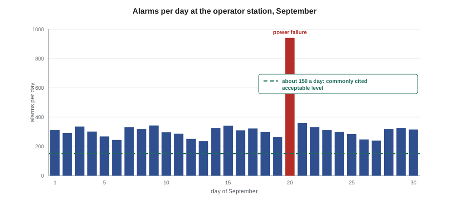
On Sunday, October 4, 2026, a quiet day shift, Pilar Quenneville printed the control system's alarm journal for the first ten minutes of the September 20 power failure and laid it on the control room desk in front of Tamar Ellingsen. It ran to four pages. "One hundred and eighty-six alarms in ten minutes," Pilar said. "I was here. I acknowledged them as fast as I could and I read maybe a dozen. The ones that mattered were drum level on boiler 1 and 2, feedwater pressure low, and the turbine starting. Everything else was the plant telling me, a hundred and seventy different ways, that the power had gone off. If something else had gone wrong at the same time, I'd never have seen it." Grazyna Wolanski had asked her to bring the journal to the November operations meeting with a proposal, and Pilar wanted Tamar's help sorting it.
This lesson covers the distributed control system (DCS) that runs a modern plant: its architecture, the operator's screens, redundancy and the separate safety systems, cybersecurity basics, and above all alarm management, the discipline of making sure every alarm is one that an operator needs to see and can act on.
From panels to distributed control
Older plants were controlled from panel boards: rows of single-loop pneumatic or electronic controllers, chart recorders, indicators and annunciator windows. Each controller was a separate box, wired directly to its transmitter and valve. That approach is easy to understand but takes up a great deal of space and makes it hard to see the plant as a whole or record what happened.
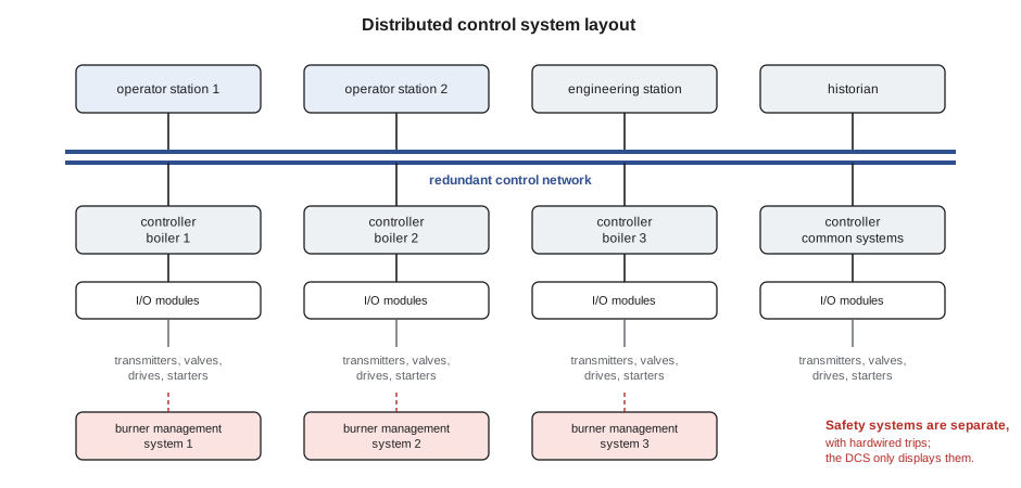
A distributed control system spreads the control functions across several controllers located near the equipment, connected by a network to operator workstations in the control room. The parts of a typical DCS are:
- Input/output (I/O) modules, which receive the 4–20 mA, thermocouple, RTD and on-off signals from the field and send outputs to valves, drives and starters.
- Controllers, processors that run the control loops, sequences and interlocks for a part of the plant. Each boiler at Cantwell has its own controller, and a fourth handles the common systems: feedwater, deaerator, hot water loop and auxiliaries.
- The control network, usually redundant Ethernet, linking controllers and workstations.
- Operator workstations running the human-machine interface (HMI): the graphic displays, trends, faceplates and alarm lists the operator uses.
- An engineering workstation, where configuration is changed, protected by passwords and change control.
- A historian, which stores process values, alarms and operator actions for months or years. The sequence-of-events record Pilar used for her September 20 log entry came from it.
A programmable logic controller (PLC) is a similar device developed for machine and sequence control; packaged equipment such as the chiller, the instrument air compressors and the water softeners often come with their own PLCs, linked to the DCS so the operator can see their status. A building automation system (BAS) does the same job for heating, ventilation and air conditioning in buildings, and a district energy plant often links to its customers' building systems.
Redundancy and failure
Because a DCS runs the whole plant, it is built so that no single failure can stop it. Controllers, power supplies and networks are usually redundant: a primary and a backup run side by side, and the backup takes over without a bump if the primary fails. Workstations are interchangeable, so the loss of one screen does not lose control. The system's own diagnostics report faults in modules, networks and power supplies as system alarms.
Even so, the operator must know what happens if the DCS is lost entirely. Field devices are chosen to fail safe: control valves go to their fail positions, as described in lesson 6, and motor starters may hold their state or trip, depending on their design. The plant's emergency procedures say how to run, or shut down, each system without the DCS: which local gauges to watch, which valves have handwheels, which motors can be started locally. A loss-of-DCS drill, carried out from time to time on a quiet shift, proves the procedure works.
Safety systems are separate
Safety functions are kept separate from the basic process control system. On a boiler, the burner management system (BMS) handles purge, ignition, flame supervision and the safety shutdowns, and the low water cutoffs and high limit pressure switches are wired directly to trip the fuel. Larger process plants have a safety instrumented system (SIS), designed to IEC 61511, with its own sensors, logic solver and final elements.
Keeping them separate means that a fault in the DCS, a configuration error or a cyber incident cannot disable the protection. The DCS shows the operator what the safety systems are doing, but it does not control them. Bypassing a safety function is never done from the DCS screen; it requires a written authorization and the controls of PWR-110 lesson 7.
The operator's screens
A good HMI helps the operator see what matters at a glance. The approach known as high-performance HMI uses muted gray backgrounds and equipment, so that color is reserved for abnormal conditions and alarms; shows values with their normal ranges, so the operator can see whether a number is good without remembering it; uses trends rather than single numbers wherever a rate of change matters; and arranges displays in a hierarchy, from a whole-plant overview down to the detail of a single pump. Older HMIs, with bright colors, animated flames and dozens of numbers on a schematic, make abnormal conditions harder to spot.
An operator should be fluent with the faceplate of a control loop: the set point, process variable and output; the mode (automatic, manual or cascade); and the alarm limits. Every change made through the HMI is recorded by the historian with the operator's user name and the time, which is one reason why operators log in under their own names and never share accounts.
Cybersecurity basics for operators
Control systems are increasingly connected to business networks, remote support and the internet, and that brings cyber risk. The operator's part in defending the control system is straightforward and important:
- Use only your own account, and lock or log off a workstation when you leave it.
- Never plug USB drives, phones or laptops into control system equipment unless the plant's procedure permits that specific device.
- Do not install software, browse the internet or read email on control system workstations.
- Treat requests for remote access, passwords or system information, by phone or email, with suspicion, and confirm them through a known contact.
- Report anything unusual: a screen behaving strangely, a setting changing without explanation, an unfamiliar device in a cabinet.
Remote access for contractors such as Sallow Creek Controls is set up by the plant, enabled only when needed, and logged. Wendeline Achterberg's remote sessions at Cantwell have to be opened from the plant end by the shift engineer.
What an alarm is for
An alarm is an audible and visible indication to the operator of an equipment malfunction, process deviation or abnormal condition requiring a timely response. The last three words are the test. The international standard for alarm management, ANSI/ISA-18.2, published internationally as IEC 62682, builds everything on that definition: if the operator does not need to do something, it should not be an alarm. It may be an event recorded in the historian, a status shown on a graphic, or a message for maintenance, but it should not sound a horn in the control room.
Too many alarms are dangerous. Investigations of major industrial accidents have repeatedly found operators facing hundreds of alarms in the minutes before the event, unable to pick out the few that mattered. The September 20 journal was a small example: most of the 186 alarms were the predictable consequence of a power failure, and they buried the ones Pilar needed.
The alarm management lifecycle
ISA-18.2 describes alarm management as a lifecycle with several stages:
- An alarm philosophy document sets the plant's rules: what qualifies as an alarm, how priorities are assigned, the colors and sounds, the performance targets, and who may change an alarm.
- Identification and rationalization: each existing or proposed alarm is reviewed by a small team, usually an experienced operator, an engineer and someone who knows the control system. For each one they record the cause, the consequence of not acting, the operator's action, the time available to act and the priority. Alarms that fail the test are removed or turned into events.
- Detailed design: set points, dead bands, delays and suppression logic are designed to make each alarm reliable.
- Implementation, operation and maintenance, with the alarm response information available to the operator.
- Monitoring and assessment: alarm rates and bad actors are measured regularly, and management of change controls every alteration.
The priority of an alarm comes from the severity of the consequence and the time available to respond. A common scheme has three priorities, with most alarms at the lowest priority: one widely used guide aims for about 80 in 100 low, 15 in 100 medium and 5 in 100 high. If everything is high priority, nothing is.
Measuring alarm performance
The usual measures of an alarm system are:
- The average alarm rate per operator. Guidance generally treats about 1 alarm per 10 minutes, about 6 an hour or 150 a day, as very likely to be acceptable, and about 2 per 10 minutes as the most manageable.
- The number and length of alarm floods, commonly defined as more than 10 alarms in 10 minutes.
- The top bad actors: the most frequent alarms, which often make up a large share of the total.
- Chattering alarms that go in and out of alarm repeatedly in a short time, and stale alarms that stay active for more than a day.
Worked problem
Cantwell's September alarm rate
The historian shows 9,850 alarms at the Cantwell operator workstation during September, a 30-day month, of which the 10 most frequent alarm tags produced 6,010. Find the average daily rate and the average per 10 minutes, and the share from the top 10.
Show solution
- Daily rate:
- \[\frac{9{,}850}{30} = 328 \text{ alarms a day}\]
- There are 144 ten-minute periods in a day:
- \[\frac{328}{144} = 2.3 \text{ alarms per 10 minutes}\]
- Share from the top 10:
- \[\frac{6{,}010}{9{,}850} = 0.61\]
Answer: About 328 a day, or 2.3 per 10 minutes on average, beyond the manageable level even before floods are counted. The top 10 tags produced 61 in 100 of all alarms, so fixing a handful of bad actors would cut the load by more than half.
Fixing nuisance alarms
Pilar and Tamar went through the top 10 list and the flood journal tag by tag. Most fell into a few familiar groups, each with a standard fix:
- Chattering alarms, like the condensate tank high level, which went in and out of alarm dozens of times a day as the level rippled around the set point. The fix is a dead band, so that the alarm clears only when the level falls a set amount below the trip point, and an on-delay, so that it sounds only if the condition lasts a few seconds.
- Duplicate alarms, where one event produces several: low feedwater pressure, low feed flow and feed pump stopped all alarming for the same pump trip. Rationalization keeps the one that tells the operator what to do.
- Consequential alarms during a known plant state, like the dozens of motor-stopped alarms after a power failure. State-based suppression hides them automatically when the control system knows the power has failed, while keeping the alarms that still need action.
- Alarms that require no action, such as a pump running or a filter changeover complete. These become events or status indications.
- Wrong set points, left over from commissioning or from a different operating mode.
Operators may also shelve an alarm, temporarily removing it from the alarm list, for example while a faulty transmitter waits for repair. Shelving must be controlled: the alarm philosophy says who may shelve, for how long, and that shelved alarms are reviewed at every shift turnover. Disabling an alarm permanently is a change and goes through management of change.
Responding to an alarm
When an alarm sounds, a disciplined operator:
- Silences the horn, which stops the noise but does not acknowledge the alarm.
- Reads the alarm: what tag, what condition, what priority.
- Acknowledges it, confirming it has been seen.
- Confirms the condition with another indication, a second instrument, a trend or a look at the equipment.
- Acts according to the alarm response procedure or the operator's training, and watches the result.
- Records significant alarms and actions in the log.
Each rationalized alarm should have alarm response information: the likely causes, how to confirm, the corrective action and the consequence of not acting, available from the alarm list with one click. For a trainee, reading the response information for every alarm on the plant is one of the fastest ways to learn how the plant behaves.
Pilar's proposal for the November meeting fitted on one page: add dead bands and delays to the four chattering tags, combine eleven duplicate feedwater alarms into three, convert nine status alarms into events, and ask Wendeline to quote for state-based suppression on loss of normal power. She estimated that the changes would cut the everyday rate by about half and the September 20 flood from 186 alarms to about 40. Grazyna added it to the agenda as a management of change item.
Common mistakes
MistakeTreating every abnormal indication as an alarm.
InsteadAn alarm needs a timely operator response; status and maintenance messages belong elsewhere.
MistakeAcknowledging alarms without reading them during a flood.
InsteadSilence the horn, then read and prioritize; look for the alarms that need action first.
MistakeShelving a nuisance alarm and forgetting it.
InsteadShelving is temporary and controlled; review shelved alarms at every turnover.
MistakeAssuming the DCS controls the burner safety shutdowns.
InsteadThe BMS and limit devices are separate safety systems with hardwired trips.
MistakePlugging a personal USB drive into an operator workstation to copy a trend.
InsteadOnly devices permitted by the plant's procedure may be connected to control system equipment.
Summary and key terms
- A DCS spreads control across controllers linked by a redundant network to operator workstations, an engineering station and a historian.
- Safety systems such as the BMS and low water cutoffs are separate from the DCS and are never bypassed from its screens.
- High-performance HMI reserves color for abnormal conditions and shows values against their normal ranges.
- Operators defend the control system by using their own accounts, connecting no unapproved devices and reporting anything unusual.
- ISA-18.2 defines an alarm as needing a timely response and sets out a lifecycle of philosophy, rationalization, monitoring and change control.
- About 1 alarm per 10 minutes is a commonly cited acceptable rate; floods, chattering and bad actors are fixed by dead bands, delays, suppression and rationalization.
- Distributed control system
- A control system in which controllers near the equipment are linked by a network to central operator workstations.
- Historian
- A database that stores process values, alarms and operator actions over time.
- Human-machine interface
- The screens and controls through which an operator monitors and operates the plant.
- Alarm rationalization
- The review of each alarm's cause, consequence, required action, response time and priority.
- Alarm flood
- A period in which alarms arrive faster than an operator can deal with them, commonly more than 10 in 10 minutes.
- Chattering alarm
- An alarm that repeatedly goes in and out of the alarm state in a short time.
- Shelving
- Temporarily removing an alarm from the operator's alarm list under controlled conditions.
Practice problems
Work each problem on paper first, then reveal the answer to check.
A plant records 4,320 alarms in a 30-day month. What is the average rate per 10 minutes?
Show answer
4,320 ÷ 30 = 144 a day; 144 ÷ 144 = 1 alarm per 10 minutes.
In one 10-minute period, 23 alarms arrive. Is this a flood by the common definition?
Show answer
Yes; more than 10 alarms in 10 minutes.
An alarm on a pump's running status sounds every time the pump starts. What should rationalization do with it?
Show answer
Remove it as an alarm; the operator needs no action, so it becomes a status indication or event.
Lesson quiz · 5 questions
Score 60% or more to complete this lesson.
Create a free account to save your progress, take quizzes and earn a certificate.