
PWR-240 · Lesson 2 of 12 · 28 min
Motors, starters and drives
▶ Video coming soon A video version of this lesson is on the way.
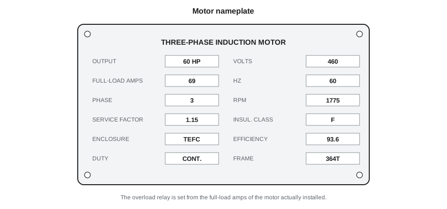
At 06:10 on Sunday, September 13, 2026, as the morning heating load came on and boiler 2 drove up toward high fire, its forced draft fan stopped. The burner tripped on loss of combustion air, the alarm sounded in the control room, and Lorne Fitzwilliam brought boiler 1 up to carry the load while Tamar Ellingsen watched the steam pressure recover. At the fan's soft starter in MCC 1 they found the overload relay tripped. Lorne did not reset it straight away. "An overload trip means the motor drew more current than the relay allows, for longer than it allows," he said. "Either the motor really was overloaded, or the relay is set wrong. We find out which before we start it again." The answer was on the motor's new nameplate: the fan motor had been replaced in August with a premium efficiency motor whose full-load current was higher than the old one's, and nobody had changed the overload setting.
Electric motors drive almost every pump, fan and compressor in a plant. This lesson covers how a three-phase induction motor works, how to read its nameplate, slip and torque, the common ways of starting a motor, overload and short-circuit protection, variable frequency drives and the operator's checks on running motors. The electrical work itself belongs to electricians; the operator's job is to run the machines well, recognize trouble and protect people and equipment.
How an induction motor works
The three-phase squirrel cage induction motor is the workhorse of industry: simple, rugged and cheap. Its stator, the stationary outer part, carries three sets of windings in slots in a laminated steel core. When three-phase current flows in them, the combined field rotates around the stator at a speed fixed by the supply frequency and the number of magnetic poles. This is the synchronous speed:
where N<sub>s</sub> is in revolutions per minute, f is the frequency in hertz and P is the number of poles. At 60 Hz a two-pole motor has a synchronous speed of 3,600 r/min, a four-pole motor 1,800 r/min and a six-pole motor 1,200 r/min.
The rotor is a laminated steel cylinder with aluminum or copper bars cast or pressed into slots and joined at each end by shorting rings, which together look like a squirrel cage. The rotating field sweeps past the bars and induces currents in them, and those currents produce a magnetic field of their own that is dragged along by the stator field. The rotor never quite catches up: if it turned at synchronous speed, the field would not cut the bars, no current would be induced and there would be no torque. The difference between the synchronous speed and the actual speed is the slip:
Worked problem
Slip of hot water pump 2
Hot water circulating pump 2 is driven by a four-pole motor with a nameplate speed of 1,780 r/min at 60 Hz. What is the slip at full load?
Show solution
- Synchronous speed:
- \[N_s = \frac{120 \times 60}{4} = 1{,}800 \text{ r/min}\]
- Slip:
- \[s = \frac{1{,}800 - 1{,}780}{1{,}800} = 0.011\]
Answer: The slip is about 0.011, or a little over 1 in 100. Slip rises roughly in proportion to load, so a lightly loaded motor runs very close to 1,800 r/min.
To reverse an induction motor, an electrician swaps any two of the three supply leads, which reverses the direction of the rotating field. That is why a motor that has had its leads disconnected for repair is always bumped briefly, with the coupling separated where possible, to check its rotation before it is put back to work. A centrifugal pump running backwards still pumps a little, but far below its rated head, and some pumps unscrew their impellers when run in reverse.
Torque and current from start to full speed
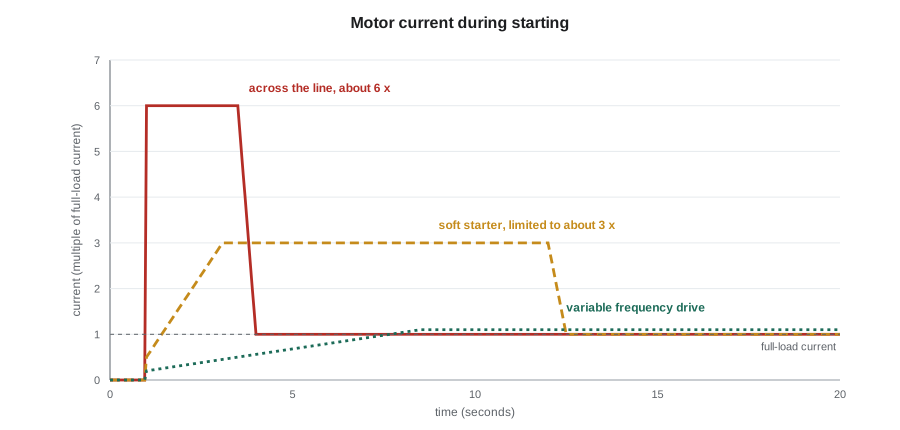
When an induction motor is first switched on, the rotor is stationary and the slip is 1. The rotor bars see the full speed of the rotating field, very large currents are induced, and the motor draws an inrush or locked-rotor current of typically 6 to 8 times its full-load current. That current lasts until the motor accelerates, a second or two for a pump, longer for a large fan with a heavy wheel. The torque produced at standstill, the locked-rotor torque, is usually 1.5 to 2.5 times full-load torque for a standard design. As the motor accelerates the torque rises to a maximum, the breakdown torque, then falls steeply to the full-load point near synchronous speed.
Those characteristics explain several operating rules. A motor should not be started over and over in quick succession, because each start heats the windings far more than an hour of running; manufacturers give a limit, such as two starts from cold or one from hot, followed by a cooling period. A motor whose load jams or whose bearing seizes behaves like a locked rotor and overheats in seconds. And a large motor starting on a weak supply, such as the standby generator, pulls the voltage down for everything else on the bus.
Reading a motor nameplate
Every motor carries a nameplate, and the operator should be able to read it without help. The main items are:
- Rated output in kilowatts or horsepower: the shaft power the motor can deliver continuously.
- Voltage, frequency and phase, and the full-load current (FLA) at that voltage.
- Full-load speed in r/min, which tells you the number of poles and the slip.
- Service factor (SF): a multiplier showing how much continuous overload the motor can carry at rated voltage and frequency without damage. A service factor of 1.15 allows 115 in 100 of rated load, though at a higher temperature and shorter insulation life. Many motors built to IEC standards have a service factor of 1.0.
- Insulation class (B, F or H) and the design temperature rise, which set the hottest temperature the windings can tolerate.
- Enclosure type: open drip-proof (ODP) for clean, dry rooms; totally enclosed fan-cooled (TEFC), the common choice in plants; explosion-proof for hazardous locations.
- Frame size, efficiency and design letter or code letters, which set the starting characteristics.
Starting methods
A starter connects a motor to the supply, disconnects it, and protects it against overload. The choice of starting method depends on the size of the motor, the strength of the supply and what the driven machine can tolerate.
- Across-the-line or direct-on-line (DOL) starting connects the motor to full voltage through a magnetic contactor. It is simple, cheap and gives full starting torque, but it draws full inrush current and gives the driven machine a mechanical jolt. Most small and medium motors in a plant start this way.
- Reduced-voltage starters lower the voltage during acceleration to cut the inrush current. Older plants use autotransformer starters and wye-delta starters, which start the motor with its windings in wye, at 1 ÷ √3 of the voltage, then switch to delta at speed.
- A soft starter uses thyristors, solid-state switches, to ramp the voltage up smoothly over a set time, often 10 to 30 seconds, and often to ramp it down when stopping, which helps prevent water hammer in pump systems. Once the motor is up to speed a bypass contactor usually closes to carry the running current and keep the thyristors cool.
- A variable frequency drive (VFD) starts the motor at low frequency and low voltage and raises both together, so the motor never draws much more than its full-load current. It also lets the motor run continuously at any speed, discussed below.
Reduced voltage reduces starting torque as well as current. Torque varies roughly with the square of the voltage, so a soft starter that applies half voltage gives only about a quarter of the full-voltage torque. That suits centrifugal fans and pumps, whose load torque is low at low speed, but it may not start a loaded conveyor or a reciprocating compressor.
The starter's control circuit, usually at 120 V from a control transformer, uses start and stop pushbuttons, a holding or seal-in contact that keeps the contactor closed once the start button is released, and the overload contacts in series with the coil. A loss of supply drops the contactor out, and with a three-wire control circuit the motor will not restart by itself when the power returns. Some motors, such as boiler feed pumps and fans, are deliberately given two-wire or automatic restart controls, so that they come back with the plant after a short dip; the plant's drawings and procedures say which is which.
Overload and short-circuit protection
A motor circuit has two separate kinds of protection, and an operator must not confuse them:
- Short-circuit and ground-fault protection, by fuses or a circuit breaker at the head of the branch circuit, deals with faults: thousands of amperes flowing through a damaged cable or a failed winding. It must act in a fraction of a second, and it must not trip on the normal starting inrush.
- Overload protection, by an overload relay in the starter, deals with a motor that is simply working too hard, drawing perhaps 120 to 150 in 100 of its full-load current. It acts slowly, over seconds or minutes, following the motor's heating.
Thermal overload relays use bimetal elements heated by the motor current; electronic overload relays measure the current with small current transformers and model the motor's heating, and many also detect phase loss and current imbalance. The relay's trip class describes how fast it trips at locked-rotor current: a class 10 relay trips within 10 seconds, a class 20 within 20 seconds. Fans with heavy wheels that take a long time to accelerate may need class 20 or 30.
The overload setting is based on the motor's nameplate full-load current, not on a table value. The National Electrical Code, as adopted in Ohio, sets the maximum setting as a percentage of the nameplate current that depends on the motor's service factor and temperature rise. Choosing and adjusting the setting is electrical work, done by a qualified electrician.
Worked problem
What tripped the forced draft fan
The new fan motor's nameplate shows 60 hp, 460 V, full-load current 69 A, service factor 1.15. The overload relay was still set at 64 A, the old motor's full-load current. At high fire the motor drew 70 A. Explain the trip, and estimate the motor's current if it had been started across the line.
Show solution
- The motor was drawing 70 ÷ 69 = 1.01 of its own full-load current: barely above rated load and well within its service factor.
- But the relay saw 70 ÷ 64 = 1.09 of its setting, enough for a thermal relay to trip after several minutes at high fire.
- An across-the-line start would draw about 6 × 69 ≈ 410 A for a few seconds; the soft starter holds it to about three times full-load current.
Answer: The relay setting, not the motor, caused the trip. Ruaridh reset the electronic overload to the new nameplate current, recorded the change on the motor record and the starter door, and the fan ran through the morning peak without trouble.
Lorne used the event to make a point to Tamar. The trip was a nuisance, but resetting a tripped overload two or three times to keep a motor running is how windings are burned out. When a protective device trips, the operator finds out why before restarting, and if the cause cannot be found, the motor stays off and the electrician is called.
Variable frequency drives
A variable frequency drive controls a motor's speed by changing the frequency of the supply. Inside, a rectifier converts the incoming AC to DC, a DC bus with large capacitors smooths it, and an inverter of fast transistor switches, insulated-gate bipolar transistors or IGBTs, rebuilds a variable frequency, variable voltage output by pulse width modulation. The drive keeps the ratio of voltage to frequency roughly constant, so that the motor's magnetic flux and torque capability stay the same at every speed.
For centrifugal pumps and fans, a VFD saves a great deal of energy. The affinity laws from PWR-230 lesson 4 say that flow varies with speed, head with speed squared and power with speed cubed. Throttling a valve or a damper to reduce flow wastes the extra head; slowing the machine removes it.
Worked problem
Savings from the hot water pump drive
Hot water pump 2 draws 24 kW at full speed. During the shoulder seasons its VFD runs it at 85 in 100 of full speed for about 4,000 hours a year. Estimate the power and the yearly energy saved compared with running at full speed.
Show solution
- Power varies with the cube of speed:
- \[P_2 = 24 \times 0.85^3 = 24 \times 0.614 = 14.7 \text{ kW}\]
- Power saved:
- \[24 - 14.7 = 9.3 \text{ kW}\]
- Energy saved:
- \[9.3 \times 4{,}000 = 37{,}000 \text{ kWh a year}\]
Answer: About 9.3 kW and 37,000 kWh a year, less a few in 100 for the drive's own losses. In practice the saving is smaller where the system has a large static head, because the cube law applies only to friction head.
Drives have their own operating concerns. They produce heat, typically 2 to 3 in 100 of the power they handle, so the room or enclosure must be kept cool and its filters clean. Their fast switching produces harmonics that distort the supply waveform and can overheat transformers and capacitor banks, and high-frequency voltage spikes that can damage motor insulation and drive current through the motor bearings, pitting the races. Motors intended for drive service, filters and shaft grounding rings deal with these. A drive's DC bus capacitors stay charged for several minutes after the drive is switched off; the drive's label gives the waiting time, and only qualified people open the enclosure.
Most drives have a bypass, a set of contactors that can run the motor directly across the line if the drive fails. An operator using the bypass must remember that the motor then runs at full speed: the pump's head rises, the system pressure goes up and the flow may be far more than the system can take. The plant procedure for hot water pump 2 says to throttle the discharge valve before switching to bypass.
Single-phase and DC motors
Plants also have small single-phase motors, on chemical feed pumps, unit heaters and tools. A single-phase winding produces a pulsating field, not a rotating one, so these motors need a starting arrangement, such as a start winding and a capacitor, cut out by a centrifugal switch near full speed. A failed start capacitor or switch leaves a motor that hums but will not turn.
Direct current motors, with brushes and a commutator, were once used wherever variable speed was needed. VFDs have largely replaced them, but they survive on some older equipment, on battery-powered emergency oil pumps for turbine bearings, and in hoists. Their brushes wear and need inspection.
When a three-phase motor loses one phase while running, through a blown fuse or a loose connection, it keeps turning on the remaining two, a condition called single phasing. It draws much higher current in the two healthy lines, overheats quickly and will not restart once stopped. Modern electronic overloads detect phase loss and trip; older thermal relays may be slow to respond. An operator who hears a motor growl more loudly than usual, sees a high current on one ammeter phase or finds a motor that hums but will not start should suspect single phasing and have it stopped.
Operator checks on running motors
On rounds, an operator checks every running motor with the same short routine:
- Listen for changes in sound: a growl, a rhythmic hum or a bearing whine.
- Feel the frame for temperature with the back of the hand only where it is safe, or better, use an infrared thermometer. A TEFC motor frame running at 60 to 80 °C can be normal; a sudden rise is not.
- Check the cooling: a TEFC motor's fan cover and cooling fins must be free of lint, dust and oil. A clogged fan cover was the cause of the condensate transfer pump motor running warm in PWR-210 lesson 11.
- Read the current on the starter ammeter or control system and compare it with the nameplate and with earlier readings.
- Look for vibration, loose guards, oil leaks from bearings, and the condition of cables and conduit at the motor terminal box.
- Record unusual readings, report them and follow up with the electrician or the maintenance planner.
Electricians add insulation resistance tests, typically before a motor is returned to service after a long shutdown or a wetting. A motor that has stood idle in a damp pump gallery can absorb enough moisture to fail its test; heaters in the windings, known as space heaters, are energized while the motor is off to prevent this. If a motor has space heaters, the operator checks they are on whenever the motor is stopped.
Common mistakes
MistakeResetting a tripped overload and restarting the motor immediately.
InsteadFind the cause first. Repeated resets can burn out a winding; if no cause is found, the motor stays off and the electrician is called.
MistakeSetting an overload from a table or the old motor's current.
InsteadThe setting comes from the nameplate of the motor actually installed, and setting it is electrical work.
MistakeRunning a pump on drive bypass without adjusting the system.
InsteadOn bypass the motor runs at full speed; throttle the discharge as the procedure says before switching over.
MistakeStarting a large motor several times in quick succession.
InsteadEach start heats the winding heavily; follow the manufacturer's limit on starts and cooling time.
MistakeAssuming a soft starter gives full starting torque.
InsteadTorque falls roughly with the square of the voltage; a soft start suits fans and centrifugal pumps, not every load.
Summary and key terms
- An induction motor's synchronous speed is 120f ÷ P; the rotor runs slightly slower, the difference being the slip.
- Starting current is typically 6 to 8 times full-load current; starts heat the windings heavily.
- The nameplate gives output, voltage, full-load current, speed, service factor, insulation class and enclosure.
- Across-the-line, reduced-voltage, soft-start and VFD starting trade cost against inrush current and torque.
- Short-circuit protection deals with faults; overload relays protect against sustained overcurrent and are set from the nameplate.
- VFDs save energy on pumps and fans by the cube law but bring harmonics, heat and stored charge.
- Synchronous speed
- The speed of the rotating magnetic field in an AC motor, equal to 120 times the frequency divided by the number of poles.
- Slip
- The difference between synchronous speed and actual rotor speed, as a fraction of synchronous speed.
- Service factor
- A nameplate multiplier showing how much continuous overload a motor can carry without damage.
- Overload relay
- A device in a motor starter that trips the motor when its current stays above the setting for too long.
- Soft starter
- A solid-state starter that ramps the motor voltage up gradually to limit inrush current and mechanical shock.
- Variable frequency drive
- An electronic controller that changes the frequency and voltage supplied to a motor to vary its speed.
- Single phasing
- Operation of a three-phase motor after the loss of one phase, which causes overheating.
Practice problems
Work each problem on paper first, then reveal the answer to check.
What is the synchronous speed of a six-pole motor on a 60 Hz supply?
Show answer
120 × 60 ÷ 6 = 1,200 r/min.
A two-pole motor runs at 3,540 r/min at full load. What is its slip?
Show answer
(3,600 − 3,540) ÷ 3,600 = 0.017, about 1.7 in 100.
A soft starter applies 60 in 100 of full voltage at the start. Roughly what fraction of full-voltage starting torque does the motor produce?
Show answer
Torque varies with voltage squared: 0.6² = 0.36, about a third.
A fan's VFD runs it at 70 in 100 of full speed. Roughly what fraction of full-speed power does it take?
Show answer
0.7³ = 0.34, about a third.
Lesson quiz · 5 questions
Score 60% or more to complete this lesson.
Create a free account to save your progress, take quizzes and earn a certificate.