
PWR-240 · Lesson 5 of 12 · 26 min
Instrumentation: pressure, level, flow and temperature
▶ Video coming soon A video version of this lesson is on the way.
On Sunday, September 27, 2026, during the morning round, Tamar Ellingsen noticed that boiler 1's drum level on the control screen read 1.5 in above normal water level, while the gauge glass on the drum showed the water almost exactly at normal. The three-element controller, believing the level was high, had trimmed the feed back, and the real level was drifting down. Lorne Fitzwilliam blew down the gauge glass to prove it, then put the feedwater valve in manual and held the level by the glass while they looked for the cause. They found it at the condensate pot at the top of the transmitter's reference leg: a weeping compression fitting had let part of the water column drain away. "A level transmitter on a drum doesn't measure level," Lorne said. "It measures a pressure difference and works out the level from it. If you change the column it's comparing against, it tells you a lie, and the controller believes it."
Every control loop, alarm and trip in a plant starts with a measurement. This lesson covers the instruments that measure the four great process variables, pressure, level, flow and temperature, how they work, how their signals reach the control system, how they are calibrated, and what typically goes wrong. PWR-220 lesson 5 introduced boiler instrumentation; this lesson goes into the principles in more depth.
Measurement terms
A few terms apply to every instrument:
- The range is the span of values an instrument is set to measure, from its lower range value to its upper range value, for example 0 to 250 psi. The span is the difference between the two.
- Accuracy is how close the reading is to the true value, usually stated as a percentage of span. Repeatability is how closely repeated readings of the same value agree. An instrument can be repeatable and still wrong, if its zero has shifted.
- Zero shift moves every reading up or down by the same amount; span error makes the error grow with the reading. Calibration corrects both.
- Response time is how quickly the instrument follows a change. Thermowells, long impulse lines and heavy damping all slow it.
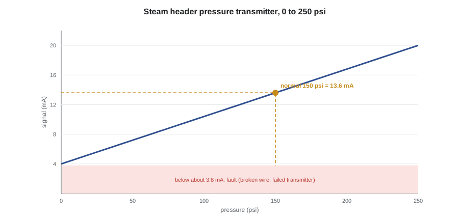
Most modern transmitters send their reading as a 4 to 20 mA current signal on a two-wire loop: 4 mA at the lower range value and 20 mA at the upper. The live zero of 4 mA lets the receiver tell a reading of zero from a broken wire, which gives 0 mA, and powers the transmitter from the loop itself. Many transmitters also carry a digital HART signal on the same pair of wires, which lets a technician read and configure the transmitter with a handheld communicator.
Worked problem
Scaling a 4–20 mA signal
The steam header pressure transmitter has a range of 0 to 250 psi. What current does it send at the normal pressure of 150 psi, and what pressure is it reading if the signal is 11.0 mA?
Show solution
- Current for a reading:
- \[I = 4 + 16 \times \frac{150}{250} = 4 + 9.6 = 13.6 \text{ mA}\]
- Reading for a current:
- \[P = \frac{11.0 - 4}{16} \times 250 = 109 \text{ psi}\]
Answer: 13.6 mA at normal pressure; 11.0 mA means about 109 psi.
Measuring pressure
Pressure can be measured as gauge pressure, relative to the atmosphere, as absolute pressure, relative to a perfect vacuum, or as differential pressure, the difference between two points. PWR-210 lesson 6 covered the units and conversions. The instruments are:
- The Bourdon tube gauge, a flattened curved tube that straightens as pressure rises and moves a pointer through a linkage. It is the common local gauge on boilers, pumps and headers. On steam service it is fitted with a siphon, a loop of pipe that fills with condensate and keeps live steam out of the tube.
- Diaphragm and bellows elements for low pressures, draft gauges and differential measurement.
- Manometers, U-tubes filled with water or another liquid, used for low draft and gas pressures and as calibration standards.
- Electronic pressure transmitters, in which the pressure deflects a thin diaphragm and a capacitance, piezoresistive or resonant sensor converts the deflection into an electrical signal.
Pressure gauges and transmitters are calibrated against a standard of known accuracy: a deadweight tester, which balances precisely known weights on a piston of known area, or a calibrated electronic reference. PWR-210 lesson 6 described Lorne's gauge calibration with a deadweight tester. A gauge should be checked at several points up and down its range, because the error may be different at each.
Measuring level
Level is measured in many ways, and a boiler drum uses several at once, because no single method is trusted alone:
- The gauge glass is a direct view of the water level, connected to the drum by top and bottom connections. It is the reference against which all other level instruments are judged, and it is blown down regularly to prove its connections are clear.
- Float and displacer instruments respond to the buoyancy of a float on the surface or of a displacer partly submerged. Float-type low water cutoffs on smaller boilers are of this type.
- Conductivity probes detect whether water or steam is in contact with an electrode; they are used for low water cutoffs and alarms.
- Differential pressure transmitters infer level from the weight of the liquid column, described below.
- Radar and guided-wave radar transmitters time a microwave pulse to the surface and back; ultrasonic transmitters do the same with sound. They are common on tanks such as the condensate tank and the fuel oil tank.
The pressure at the bottom of a liquid column depends only on its height and density:
Worked problem
Level in the condensate tank
The vented condensate tank holds water at about 195 °F, specific gravity 0.96. A differential pressure transmitter at the bottom of the tank reads 74.9 inches of water column. What is the level above the transmitter connection?
Show solution
- A column of water at specific gravity 1.0 one inch high gives one inch of water column, so:
- \[h = \frac{74.9}{0.96} = 78 \text{ in} = 6.5 \text{ ft}\]
Answer: The level is about 78 in, or 6.5 ft, above the connection. If the water cooled to 70 °F, the same level would read slightly higher, because cold water is denser.
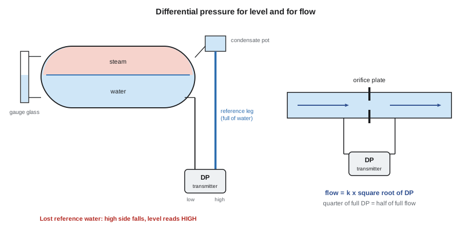
A boiler drum is under pressure, so its level transmitter compares the column of water in the drum with a reference leg: a column of water of fixed height, kept full by a condensate pot at the top that is connected to the steam space. The reference leg is connected to the high-pressure side of the transmitter and the drum water connection to the low side. As the drum level rises, the pressure on the low side rises toward the reference pressure and the difference falls; the transmitter is configured so that a smaller difference means a higher level.
That arrangement explains Tamar's discovery. When part of the reference leg drained away, the pressure on the high side fell, the difference got smaller, and the transmitter read a level higher than the real one. The fault is dangerous because it is in the unsafe direction: a controller that thinks the level is high cuts the feed, and the real level falls. Drum level transmitters are also affected by the density of the drum water and steam, which changes with pressure, so the control system applies density compensation using the drum pressure. During a cold start-up the compensated reading and the gauge glass can disagree until the boiler is near operating pressure.
Measuring flow
The commonest flow instrument in older plants is the differential pressure meter: an orifice plate, flow nozzle or venturi tube creates a restriction in the pipe, and a transmitter measures the pressure drop across it. The drop varies with the square of the flow, so the flow is proportional to its square root:
The square root is taken either in the transmitter or in the control system. Steam flow meters on boiler outlets also apply pressure and temperature compensation, because the density of steam varies with both.
Worked problem
Reading a square-root flow signal
Boiler 2's steam flow transmitter is ranged 0 to 250 inches of water differential for 0 to 26,000 lb/h. The differential pressure is 62.5 inches of water. What is the steam flow?
Show solution
- Flow is proportional to the square root of the differential pressure:
- \[Q = 26{,}000 \times \sqrt{\frac{62.5}{250}} = 26{,}000 \times 0.5 = 13{,}000 \text{ lb/h}\]
Answer: A quarter of the full differential pressure means half of full flow. The square root relationship also means that DP meters are poor at low flows: at 10 in 100 of full flow the differential is only 1 in 100 of span, and small zero errors make large flow errors.
Other flow meters avoid the square root and the permanent pressure loss of an orifice:
- Vortex meters count the vortices shed by a bluff body in the stream; their frequency is proportional to velocity. They are common on steam and condensate.
- Magnetic flow meters measure the voltage induced in a conducting liquid moving through a magnetic field. They need a conductive liquid, so they work on city water and boiler water but not on very pure condensate or oil.
- Ultrasonic meters time sound pulses through the liquid with and against the flow; clamp-on types can be fitted to the outside of a pipe for a temporary survey.
- Turbine meters, positive displacement meters and Coriolis mass flow meters are used for fuel oil, chemicals and custody transfer. The utility's gas meter is usually a rotary or turbine meter with temperature and pressure correction.
Measuring temperature
Temperature instruments in a plant include liquid-in-glass and bimetallic dial thermometers for local reading, and two kinds of electrical sensor for transmitters:
- A thermocouple is two wires of different metals joined at the measuring end. A temperature difference between the measuring junction and the reference junction at the instrument produces a small voltage, about 41 µV per kelvin for the common type K (chromel and alumel). Thermocouples are robust, cheap, cover a very wide range and are used for flue gas, furnace and stack temperatures. They must be connected with matching extension wire; ordinary copper wire creates new junctions and false readings.
- A resistance temperature detector (RTD) uses the rise in resistance of a fine platinum wire or film with temperature. The standard Pt100 has a resistance of 100 Ω at 0 °C rising by about 0.385 Ω per kelvin. RTDs are more accurate and stable than thermocouples over moderate temperatures and are used for feedwater, hot water supply and return, bearing and winding temperatures. Three- and four-wire connections cancel the resistance of the leads.
Worked problem
RTD resistance
What is the resistance of a Pt100 RTD in the deaerator outlet at 221 °F, which is 105 °C?
Show solution
- Use the linear approximation with α = 0.00385 per kelvin:
- \[R = 100 \times (1 + 0.00385 \times 105) = 140.4 \, \Omega\]
Answer: About 140.4 Ω. A reading of 0 Ω or a very high resistance means a shorted or open sensor; the transmitter detects these and sends an out-of-range signal.
Sensors are usually installed in a thermowell, a closed tube welded or screwed into the pipe, so that the sensor can be removed without opening the process. The well protects the sensor but slows its response, and a sensor that is not pushed to the bottom of its well or has lost its contact paste reads low and slow. Thermowells in fast-flowing steam can fail by vibration if they are too long for the velocity; replacement wells must match the original design.
Calibration and common faults
Instruments drift. Each plant keeps a calibration schedule in its maintenance system, with intervals set by how critical the instrument is: safety-related transmitters, such as those feeding drum level trips, are checked more often than local gauges. Calibration compares the instrument with a reference at several points, typically 0, 25, 50, 75 and 100 in 100 of span, going up and coming down, and records the readings before and after adjustment. The as-found readings show how far the instrument had drifted, which is the evidence for whether the interval is right.
Faults that operators meet most often are not inside the transmitter at all, but in what connects it to the process:
- Blocked or leaking impulse lines, from sludge, scale or freezing. Impulse lines on outdoor tanks need heat tracing in winter.
- Gas in liquid lines or liquid in gas lines, which add a false head. Liquid impulse lines slope continuously so that bubbles rise away from the transmitter.
- Lost reference legs on drum and tank level transmitters, as on boiler 1.
- Valve manifolds left in the wrong position after a calibration. A three-valve manifold has two block valves and an equalizing valve; if the equalizer is left open, the transmitter reads zero differential.
- Wiring and power faults, which show as signals below 4 mA or above 20 mA.
When a reading does not make sense, the operator compares it with another measurement of the same thing: the gauge glass against the transmitter, the local gauge against the control screen, steam flow against feedwater flow, a hand-held thermometer against the RTD. If they disagree, the operator trusts the direct measurement, takes the affected loop into manual if it is controlling the process, and reports the fault.
On boiler 1, Lorne isolated the transmitter with its manifold, Fenella Thorncroft's crew replaced the leaking fitting the same morning, and Lorne refilled the reference leg through the condensate pot's fill connection under the plant procedure, then let it stabilize for half an hour. The transmitter and the gauge glass agreed again within 0.2 in. He returned the feedwater controller to automatic and wrote the event in the log, and Grazyna Wolanski added the reference leg fittings on all three boilers to the next monthly check.
Common mistakes
MistakeTrusting the control screen over the gauge glass.
InsteadThe gauge glass is the direct measurement; if the two disagree, believe the glass and take the loop to manual.
MistakeReading a DP flow signal as if flow were proportional to differential pressure.
InsteadFlow varies with the square root of the differential; a quarter of full DP is half of full flow.
MistakeForgetting that a drained reference leg makes a drum level read high.
InsteadLoss of the reference column reduces the high-side pressure; the reading goes high and the real level can fall.
MistakeLeaving a transmitter's equalizing valve open after calibration.
InsteadWith the equalizer open the transmitter reads zero differential; check manifold positions before returning to service.
MistakeJoining a thermocouple with copper wire.
InsteadUse matching extension wire; dissimilar metals create new junctions and false readings.
Summary and key terms
- Transmitters send 4–20 mA signals; 4 mA is zero, and a signal below about 3.8 mA indicates a fault.
- Pressure is measured by Bourdon tubes, diaphragms and electronic transmitters, calibrated against a deadweight tester or reference.
- Level is measured by gauge glasses, floats, probes, radar and DP transmitters; drum DP transmitters depend on a full reference leg.
- DP flow meters follow Q = k√ΔP; vortex, magnetic, ultrasonic and Coriolis meters avoid the square root.
- Thermocouples suit high temperatures; RTDs are more accurate at moderate temperatures; both usually sit in thermowells.
- Most faults are in impulse lines, reference legs, manifolds and wiring; compare with a second measurement before acting.
- Span
- The difference between the upper and lower range values of an instrument.
- Transmitter
- An instrument that measures a process variable and sends a standard signal, usually 4–20 mA, to the control system.
- Reference leg
- A column of liquid of fixed height used as the comparison pressure for a differential pressure level transmitter.
- Orifice plate
- A plate with a hole that restricts a pipe so that the pressure drop across it can be used to measure flow.
- Thermocouple
- A temperature sensor made of two dissimilar metal wires that produce a voltage depending on temperature.
- RTD
- A resistance temperature detector, whose platinum element increases in resistance with temperature.
- Thermowell
- A closed tube installed in a pipe or vessel to hold a temperature sensor.
Practice problems
Work each problem on paper first, then reveal the answer to check.
A level transmitter ranged 0 to 10 ft sends 10.0 mA. What level does it indicate?
Show answer
(10.0 − 4) ÷ 16 × 10 = 3.75 ft.
A DP flow meter reads 49 in 100 of its differential span. What fraction of full flow is that?
Show answer
√0.49 = 0.70, or 70 in 100 of full flow.
What is the resistance of a Pt100 RTD at 140 °F, which is 60 °C?
Show answer
100 × (1 + 0.00385 × 60) = 123.1 Ω.
Lesson quiz · 5 questions
Score 60% or more to complete this lesson.
Create a free account to save your progress, take quizzes and earn a certificate.