
PWR-240 · Lesson 1 of 12 · 29 min
Electrical theory for power engineers
▶ Video coming soon A video version of this lesson is on the way.
On Saturday, September 12, 2026, at the end of her first week at Cantwell Energy Center, Tamar Ellingsen followed Ruaridh Brasseur, the electrician who looks after the plant's motors and switchgear, into the main electrical room. Ruaridh had come in on a quiet weekend morning to replace a failed contactor in the capacitor bank on motor control center 2. Before he opened anything he pointed at the power meter on the door of the bank. "Power factor 0.80," he said. "Last week it was 0.95. Three of the five steps are off line because one contactor burned out and the controller locked the others out. The utility bills us for that, and every cable from the transformer to the MCC is carrying more current than it needs to. By the end of today you should be able to tell me why."
Power engineers are not electricians, and nothing in this course qualifies anyone to work on live electrical equipment. But a plant runs on electricity, and the operator who understands voltage, current, power and power factor reads a motor nameplate, an ammeter or a utility bill with understanding rather than guesswork. PWR-210 lesson 11 introduced basic electricity for the plant. This lesson builds on it: direct and alternating current, the relationships between voltage, current, resistance and power, three-phase systems, power factor and how it is corrected, transformers, and the meters an operator reads every day.
Charge, current, voltage and resistance
Electric current is the flow of electric charge through a conductor. It is measured in amperes (A). One ampere is a flow of one coulomb of charge each second. In a metal wire the moving charges are electrons, which drift slowly through the metal while the energy they carry moves along the circuit almost at the speed of light.
Voltage, or potential difference, is the push that drives current around a circuit. It is the energy given to each coulomb of charge, measured in volts (V): one volt is one joule per coulomb. A battery, a generator or a transformer secondary is a source of voltage; a lamp, a heater or a motor winding is a load that uses the energy.
Resistance is the opposition a material offers to current. It is measured in ohms (Ω). Copper and aluminum have low resistance and are used for conductors; rubber, plastics, porcelain and glass have very high resistance and are used as insulation. The resistance of a conductor rises with its length, falls with its cross-sectional area and rises with its temperature, which is why a long, small or hot cable drops more voltage than a short, large or cool one.
The three are related by Ohm's law:
where V is in volts, I in amperes and R in ohms. If any two are known, the third follows. A 120 V control circuit feeding a relay coil of 2,400 Ω draws 0.05 A, or 50 mA; the same coil on a 24 V circuit would draw only 10 mA and might not pull in. That is why a replacement coil must match the control voltage on its label.
Electrical power and energy
Power is the rate at which electrical energy is converted to heat, light or work. In a direct current circuit, or an alternating current circuit with a purely resistive load:
with P in watts. The I²R form explains why current matters so much: doubling the current through a cable quadruples the heat produced in it. A loose lug at a motor terminal has a small resistance, perhaps a few thousandths of an ohm, but at full load current it can dissipate enough heat to char the insulation. Ruaridh's thermal camera survey each spring looks for exactly those warm connections.
Energy is power multiplied by time. The utility bills it in kilowatt-hours (kWh): one kilowatt for one hour, or 3.6 MJ. A 7.5 kW load running for 8 hours uses 60 kWh.
Worked problem
A heater element
A 480 V single-phase heater element in the fuel oil tank has a resistance of 46 Ω when hot. What current does it draw and what power does it produce?
Show solution
- Current from Ohm's law:
- \[I = \frac{V}{R} = \frac{480}{46} = 10.4 \text{ A}\]
- Power:
- \[P = V I = 480 \times 10.4 \approx 5{,}000 \text{ W} = 5.0 \text{ kW}\]
Answer: The element draws about 10.4 A and produces 5.0 kW.
Series and parallel circuits
In a series circuit the loads are connected one after another, so the same current flows through each. The total resistance is the sum of the individual resistances, and the supply voltage divides among them. Safety devices are wired in series with the thing they protect: a fuse, an overload contact or a low water cutoff switch opens the single path and stops everything downstream. A boiler's burner safety circuit is a series string of limit switches, and any one of them opening shuts the burner down.
In a parallel circuit each load is connected directly across the supply, so each gets the full voltage and draws its own current. The total current is the sum of the branch currents. Lighting, receptacles and motor branch circuits are all in parallel, so one lamp failing does not put out the others. The equivalent resistance of parallel loads is always less than the smallest branch resistance:
Alternating current
Almost all plant power is alternating current (AC), in which the voltage and current reverse direction many times a second, following a sine wave. In North America the frequency is 60 hertz (Hz): 60 complete cycles a second. AC is used because its voltage can be raised and lowered easily with transformers, and because induction motors run on it without brushes or commutators.
Because an AC voltage is always changing, it is described by its root mean square (RMS) value: the steady DC value that would produce the same heating in a resistor. For a sine wave the RMS value is the peak value divided by √2, or about 0.707 of the peak. When a plant says a supply is 480 V, it means the RMS value; the peak is about 679 V. Meters, nameplates and drawings all use RMS values unless they say otherwise.
In a circuit with only resistance, current and voltage rise and fall together; they are in phase. Coils and capacitors behave differently:
- An inductor, such as a motor winding or a transformer coil, opposes changes in current. The current lags the voltage, by up to a quarter cycle (90°) in a pure inductor. The opposition is called inductive reactance, X<sub>L</sub> = 2πfL, measured in ohms; it rises with frequency.
- A capacitor, two conducting plates separated by insulation, stores charge. The current leads the voltage by up to 90°. Its opposition, capacitive reactance X<sub>C</sub> = 1 ÷ (2πfC), falls as frequency rises.
The combined opposition of resistance and reactance is called impedance, Z, also in ohms, and Ohm's law in AC circuits becomes V = IZ.
Three-phase systems
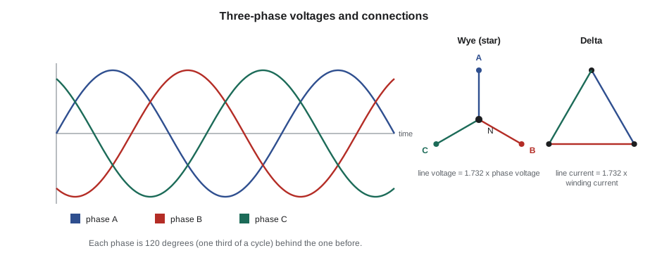
Industrial and commercial plants are supplied with three-phase power: three AC voltages of the same size and frequency, each 120° apart. A three-phase motor gets a smooth, rotating push from the three phases, starts itself without help, and uses less copper for the same power than a single-phase machine. Three-phase supplies are connected in one of two ways:
- A wye (star) connection joins one end of each winding at a common neutral point. The voltage between any two lines, the line voltage, is √3 times the voltage from line to neutral. A 480Y/277 V system has 277 V from each line to neutral, used for lighting, and 480 V between lines for motors.
- A delta connection joins the windings end to end in a triangle. The line voltage equals the winding voltage, and the line current is √3 times the winding current.
For a balanced three-phase load, whatever the connection:
where V<sub>L</sub> and I<sub>L</sub> are the line voltage and current and pf is the power factor, explained below. The apparent power, the product of voltage and current without the power factor, is √3 V<sub>L</sub> I<sub>L</sub> and is measured in volt-amperes (VA) or kilovolt-amperes (kVA).
Worked problem
Current drawn by the condensate transfer pump motor
The condensate transfer pump motor is rated 10 hp output at 460 V, three-phase. At full load its efficiency is 0.89 and its power factor 0.84. What line current does it draw?
Show solution
- Convert the output to kilowatts and find the input:
- \[P_{in} = \frac{10 \times 0.746}{0.89} = 8.38 \text{ kW}\]
- Rearrange the three-phase power equation for current:
- \[I = \frac{P}{\sqrt{3} \, V \, \text{pf}} = \frac{8{,}380}{1.732 \times 460 \times 0.84} \approx 12.5 \text{ A}\]
Answer: About 12.5 A per line. The nameplate shows 12.6 A, which agrees.
Real, reactive and apparent power
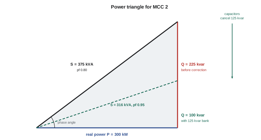
A motor needs two kinds of current. One part does work: it turns the shaft and supplies the losses. The other part builds the magnetic field in the iron every half-cycle and returns it to the supply in the next. That magnetizing current flows back and forth along the cables without doing any useful work, but it still heats the conductors and loads the transformer. The two parts combine into three quantities:
- Real power (P), in kilowatts (kW), does the work and turns the meter that the utility bills in kWh.
- Reactive power (Q), in kilovolt-amperes reactive (kvar), sustains the magnetic fields of motors and transformers.
- Apparent power (S), in kilovolt-amperes (kVA), is what the cables, switchgear and transformers must actually carry.
They form a right-angled power triangle:
where φ is the phase angle between voltage and current. A power factor of 1.0 means all the current does work. A lightly loaded induction motor may run at 0.5 or lower, because the magnetizing current stays nearly the same while the working current falls. A plant full of motors typically runs at 0.75 to 0.85 without correction.
Why power factor matters
Low power factor costs the plant in three ways. First, most utilities bill large customers for demand in kVA, or charge a penalty when the power factor falls below a set value, often 0.90. Second, the extra current heats every cable, busbar and transformer between the service and the load, wasting energy as I²R losses and using up capacity that could carry real load. Third, the extra current increases the voltage drop along the feeders, so motors at the end of a long run see a lower voltage, draw more current and run hotter.
The usual cure is power factor correction with capacitors. A capacitor draws a leading current that cancels part of the motors' lagging magnetizing current, so the reactive power circulates locally between the capacitor and the motors instead of traveling back to the utility. Capacitors can be installed at individual large motors, switched on and off with them, or grouped in an automatic bank at a motor control center or the main switchboard, where a controller switches steps in and out to hold a target power factor. Cantwell's banks are the automatic kind, with five steps of 25 kvar on each MCC.
Worked problem
Sizing the capacitor bank on MCC 2
MCC 2 carries 300 kW at a power factor of 0.80 on a 480 V supply. How much capacitance, in kvar, would raise the power factor to 0.95, and how does the line current change once the full 125 kvar bank is back in service?
Show solution
- Reactive power now: tan(cos⁻¹ 0.80) = 0.750, so
- \[Q_1 = 300 \times 0.750 = 225 \text{ kvar}\]
- Reactive power at 0.95: tan(cos⁻¹ 0.95) = 0.329, so
- \[Q_2 = 300 \times 0.329 = 98.6 \text{ kvar}\]
- Capacitance needed:
- \[Q_C = 225 - 98.6 = 126 \text{ kvar}\]
- With 125 kvar in service, Q = 100 kvar, so S = √(300² + 100²) = 316 kVA and pf = 0.949.
- Line current before and after:
- \[I_1 = \frac{375{,}000}{1.732 \times 480} = 451 \text{ A} \qquad I_2 = \frac{316{,}000}{1.732 \times 480} = 380 \text{ A}\]
Answer: About 126 kvar is needed; the 125 kvar bank gives a power factor of about 0.95 and cuts the current from about 451 A to about 380 A, a reduction of about 16 in 100.
The I²R losses in the feeder fall with the square of the current: (304 ÷ 361)² = 0.71, so the cable losses drop by nearly 30 in 100. That was Ruaridh's point at the start of the morning.
Capacitors bring their own hazards. A capacitor stores charge and can hold a lethal voltage after it is disconnected. Banks are fitted with discharge resistors that bleed the voltage down within a set time, usually about a minute, but an electrician still waits, tests and grounds the terminals before touching them. Over-correction is also a problem: a bank that stays fully in service when the motors stop pushes the power factor leading and can raise the voltage. That is why automatic banks switch steps out as load falls, and why a capacitor wired directly to a motor must be sized so it cannot over-excite the motor when it is switched off.
Transformers
A transformer changes AC voltage from one level to another. Two coils, the primary and the secondary, are wound on a common laminated iron core. The alternating current in the primary sets up an alternating magnetic flux in the core, and the flux induces a voltage in the secondary. The voltages are in the ratio of the numbers of turns, and the currents in the inverse ratio, because the power in equals the power out less small losses:
Cantwell takes its supply from the utility at 13.2 kV and steps it down to 480 V through a 2,500 kVA oil-filled transformer in the yard. Smaller dry-type transformers inside the plant step 480 V down to 120/208 V for lighting, receptacles and the control system.
Transformers are very efficient, typically 97 to 99 in 100 at full load, but the losses they do have appear as heat in the core and windings. Operators check transformer temperature gauges, oil levels and the sound of the core on their rounds. A rise in temperature with no rise in load, or a new buzzing or crackling sound, is reported to the electrician at once.
Small control transformers feed the 120 V control circuits of motor starters. Instrument transformers let meters and protective relays measure high voltages and large currents safely: a potential transformer (PT) steps the voltage down to about 120 V, and a current transformer (CT) produces a small secondary current, usually 5 A or 1 A at rated primary current. The secondary of a CT must never be opened while the primary carries current, because the CT then tries to drive its current through an open circuit and can develop a dangerous voltage. Only a qualified electrician shorts or isolates CT circuits.
Meters the operator reads
An operator reads electrical quantities every shift, mostly from fixed panel meters and the plant's control system. The common ones are:
- Ammeters, on each large motor starter and at the MCC incomers, show line current. A motor drawing more than its nameplate full-load current is overloaded, has a low supply voltage or has a mechanical fault.
- Voltmeters, usually with a selector switch to read each line-to-line voltage in turn. The three phases should agree within a few volts; an imbalance of more than about 1 in 100 heats motors disproportionately.
- Power meters and power quality meters at the main switchboard and the MCCs show kW, kvar, kVA, power factor, demand and energy.
- Frequency meters and synchroscopes on the standby generator panel, covered in lesson 3.
Electricians also use portable instruments: the multimeter, the clamp-on ammeter, which measures current without breaking the circuit, and the insulation resistance tester, which applies a test voltage of 500 V or 1,000 V DC to check the insulation of a motor winding or a cable. An operator may use a clamp-on ammeter on a running motor's cables only where the plant's electrical safety program allows it and with the protective equipment it specifies, a subject taken up in lesson 4.
| Quantity | Symbol | Unit | Plant example |
|---|---|---|---|
| Current | I | ampere (A) | Motor line current on an ammeter |
| Voltage | V | volt (V) | 480 V between lines at an MCC |
| Resistance | R | ohm (Ω) | Heater element or relay coil |
| Impedance | Z | ohm (Ω) | Motor winding at 60 Hz |
| Real power | P | kilowatt (kW) | MCC load on a power meter |
| Reactive power | Q | kvar | Magnetizing load of motors |
| Apparent power | S | kVA | Transformer and generator rating |
| Energy | E | kilowatt-hour (kWh) | The utility meter |
Back on MCC 2
By early afternoon Ruaridh had replaced the contactor, reset the controller and watched it bring all five steps back in as the afternoon load climbed. The meter on the bank door settled at 0.95. Tamar wrote the readings in her notebook, then worked the numbers with him at the electrical room desk: 361 A before, 304 A after, and nearly a third less heat in the feeder. Ruaridh added a work order to check the bank's contactors and fuses every quarter rather than once a year, since the failed contactor had been pitted badly enough that it should have been caught earlier. Lorne Fitzwilliam, reading the log entry that evening, added one line of his own: the operators would now note the MCC power factors on the daily electrical round, so that a failed step would show up within a day instead of on the next utility bill.
Common mistakes
MistakeAssuming a three-phase motor's current is its kilowatt rating divided by its voltage.
InsteadUse I = P ÷ (√3 × V × pf × efficiency) for a motor's output rating; the √3, the power factor and the efficiency all matter.
MistakeThinking a low power factor wastes energy at the load.
InsteadThe motor's real power is unchanged; the extra current wastes energy in the cables and transformers and uses up their capacity.
MistakeTreating a disconnected capacitor as safe to touch.
InsteadCapacitors hold charge; only a qualified person, after the discharge time, tests and grounds them before any work.
MistakeOpening a current transformer secondary to remove a meter.
InsteadA CT secondary is shorted by a qualified electrician first; an open CT secondary can develop a dangerous voltage.
MistakeReading a peak voltage as the supply voltage.
InsteadNameplates, drawings and meters give RMS values; the peak of a sine wave is √2 times the RMS value.
Summary and key terms
- Ohm's law, V = IR, links voltage, current and resistance; power is P = VI = I²R in resistive circuits.
- AC is described by RMS values; coils make current lag the voltage and capacitors make it lead.
- Three-phase power is P = √3 V<sub>L</sub> I<sub>L</sub> pf; apparent power in kVA is what equipment must carry.
- Real, reactive and apparent power form the power triangle; power factor is P ÷ S.
- Capacitor banks correct low power factor, cutting current, losses and demand charges, but they store dangerous charge.
- Transformers change voltage in the ratio of their turns; CT secondaries must never be opened under load.
- Impedance
- The total opposition of resistance and reactance to alternating current, in ohms.
- Power factor
- The ratio of real power to apparent power, equal to the cosine of the phase angle between voltage and current.
- Reactive power
- Power that sustains the magnetic fields of motors and transformers, measured in kvar; it does no useful work.
- Apparent power
- The product of voltage and current in an AC circuit, in kVA; the load that cables and transformers must carry.
- RMS value
- The steady value of an alternating voltage or current that produces the same heating as a direct value of that size.
- Current transformer
- An instrument transformer that produces a small secondary current in proportion to a large primary current for meters and relays.
Practice problems
Work each problem on paper first, then reveal the answer to check.
A 120 V relay coil has a resistance of 1,600 Ω. What current does it draw?
Show answer
I = 120 ÷ 1,600 = 0.075 A, or 75 mA.
A 480 V three-phase motor draws 40 A at a power factor of 0.86. What real power does it take from the supply?
Show answer
P = 1.732 × 480 × 40 × 0.86 ≈ 28,600 W, or about 28.6 kW.
A load of 200 kW runs at 0.75 power factor. How many kvar of capacitors raise it to 0.95?
Show answer
Q₁ = 200 × 0.882 = 176 kvar; Q₂ = 200 × 0.329 = 66 kvar; about 110 kvar.
A transformer has 2,750 primary turns and 100 secondary turns. With 13.2 kV on the primary, what is the secondary voltage?
Show answer
13,200 × 100 ÷ 2,750 = 480 V.
Lesson quiz · 5 questions
Score 60% or more to complete this lesson.
Create a free account to save your progress, take quizzes and earn a certificate.