
INS-420 · Lesson 2 of 12 · 25 min
Reading drawings for takeoff
▶ Video coming soon A video version of this lesson is on the way.
Raj's first evening with Priya on the Ridgemount bid started with a stack of drawings and a box of colored highlighters. "A takeoff is just counting," he said, "but counting the right things in the right order, so nothing gets missed and nothing gets counted twice." He gave her the level 2 classroom wing heating plan and kept the plumbing plans for himself. They would compare totals at the end of the week.
A takeoff is the measured list of everything to be insulated: lengths of pipe by system, size and insulation thickness; fittings, valves and specialties by size; areas of duct and equipment; and any special items. It is the base of the whole estimate, because every material and labor figure is calculated from it. This lesson covers the drawings an estimator reads, how to scale them, the order of a takeoff and the checks that catch the common errors. Lesson 3 covers measuring on site, where there are no drawings or the drawings cannot be trusted.
The drawings an insulation estimator uses
A mechanical drawing set usually contains:
- Legend and abbreviations sheet: the symbols and line types for each system (for example HWS and HWR for heating water supply and return, CHWS and CHWR for chilled water, DCW, DHW and DHWR for domestic water, ST for storm), valve and fitting symbols, and the general notes.
- Floor plans for each system and level, usually at 1/8 in = 1 ft for the building and 1/4 in = 1 ft for mechanical rooms and busy areas. Plans show horizontal runs, sizes, risers (marked where pipes go up or down) and equipment.
- Riser diagrams and schematics: a vertical, not-to-scale view of each system showing how floors connect, with pipe sizes. Riser lengths come from the floor-to-floor heights, not from measuring the diagram.
- Sections and details: cut views showing elevations, ceiling heights, typical connections and the insulation details the engineer wants, such as how to finish at a valve or at a hanger.
- Schedules: tables of equipment (tanks, heat exchangers, pumps, air handling units) with sizes and operating conditions, and sometimes an insulation schedule that gives thickness by system and pipe size.
The architectural drawings matter too. Reflected ceiling plans show ceiling heights and types, which affect access and labor (lessons 5 and 6). Room finish schedules show which areas have exposed piping, which often needs a different jacket. Structural drawings show beams and joists that pipes and ducts must cross.
On Ridgemount, the insulation thicknesses were set by a table in the specification, by system and pipe size, as INS-410 described. The drawings showed where the pipe ran and how big it was. Priya copied the thickness table onto the front page of her takeoff so she could mark each run with its thickness as she went.
Scale
Every plan is drawn to a scale, written in the title block and often beside each view. A scale of 1/8 in = 1 ft means 1/8 in on the drawing is 1 ft in the building. To measure a length, use a scale rule set to the drawing's scale, or measure in ordinary units and convert.
Worked problem
Scaling a run
A heating main measures 3 5/8 in on a plan drawn at 1/8 in = 1 ft. How long is it? How long would it be if the same measurement were taken on a 1/4 in = 1 ft detail?
Show solution
- At 1/8 in = 1 ft, each inch on the drawing is 8 ft: 3.625 in × 8 = 29.0 ft.
- At 1/4 in = 1 ft, each inch is 4 ft: 3.625 × 4 = 14.5 ft.
Answer: 29.0 ft at the building scale. The same paper length means half as much at the larger detail scale, which is why the scale must be checked on every view.
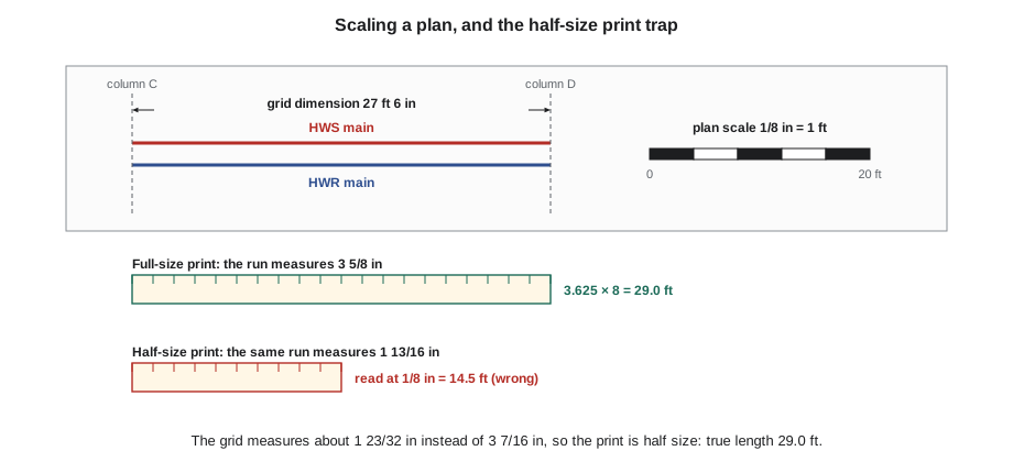
Prints are often made at a reduced size, such as half size, to save paper. A ruler set to the drawing's stated scale then gives half the real length. The safe habits are:
- Check the scale bar, if the drawing has one, against your ruler before measuring anything.
- Check a known dimension, such as a column grid spacing written on the drawing, against a measurement.
- Write the scale you used at the top of each takeoff sheet.
Worked problem
The half-size print
Priya measured a run as 1 13/16 in on a print labeled 1/8 in = 1 ft and wrote down 14.5 ft. The column grid on the same sheet is dimensioned at 27 ft 6 in but measured 1 23/32 in. What is the real length of the run?
Show solution
- At true 1/8 in = 1 ft scale, 27.5 ft would measure 3 7/16 in; it measures about 1 23/32 in, so the print is half size.
- The real scale of the print is 1/16 in = 1 ft.
- 1.8125 in × 16 = 29.0 ft.
Answer: 29.0 ft, twice what she first wrote. A grid check takes ten seconds and saves a takeoff.
Most estimators now take off from PDF drawings on screen, with takeoff software that measures lengths and counts symbols once the scale is calibrated. The same rules apply: calibrate on a known dimension, not on the stated scale, and check one length by hand. Software makes counting faster, but it also makes a wrong calibration wrong everywhere at once.
Working through a takeoff
A good takeoff follows a fixed order so that nothing is missed. Raj's order for a building is:
- One system at a time, in the order of the specification's thickness table: domestic cold, domestic hot and recirculation, heating hot water, chilled water, condensate, storm, then ducts and equipment.
- One floor or area at a time within each system, starting at the main and working out to the branches.
- By size and thickness within each run, because each size and thickness is a different material and a different labor unit.
- Mark each run as it is measured, with a highlighter on paper or a color on screen, so that a glance shows what is left.
- Count fittings and valves on the same pass, by size, as you measure the pipe they sit on.
- Add the vertical pipe from the risers and sections: each riser's length is the floor-to-floor height times the number of floors it crosses, plus offsets.
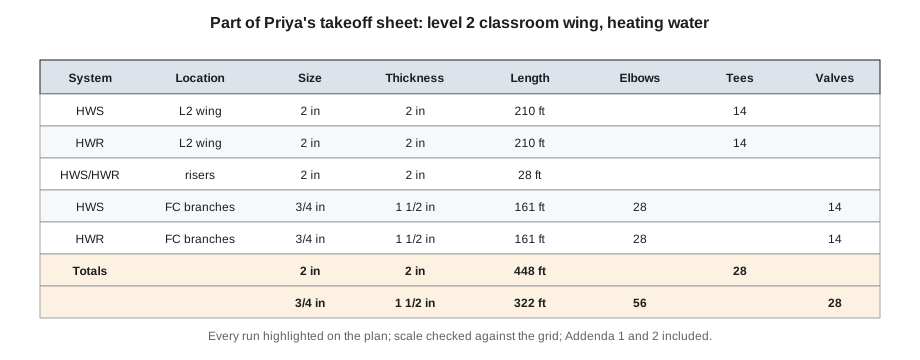
The takeoff sheet is a table. Each line is one system, size and thickness, with its measured lengths added up and its fittings counted. At the bottom of each system, the estimator totals the lengths and counts and carries them to the estimate. Coldstream's takeoff sheets also have a column for location, so that the totals can later be split into the work areas and phases the schedule needs (lesson 7).
Worked problem
Priya's level 2 wing takeoff
On the level 2 classroom wing heating plan, Priya measured the heating water supply and return mains at 210 ft each, 2 in. There are 14 fan coil branches, each with a supply and a return pipe of 3/4 in, averaging 11.5 ft each. The supply and return rise from level 1 through the 14 ft floor-to-floor height. Each branch pair has four elbows, two isolation valves and two tees on the mains. What are her totals?
Show solution
- 2 in mains: 2 × 210 = 420 ft; risers: 2 × 14 = 28 ft; total 448 ft at 2 in thickness.
- 3/4 in branches: 14 × 2 × 11.5 = 322 ft at 1 1/2 in thickness.
- Elbows: 14 × 4 = 56 (3/4 in). Valves: 14 × 2 = 28 (3/4 in). Tees: 14 × 2 = 28 (on the 2 in mains).
Answer: 448 ft of 2 in, 322 ft of 3/4 in, 56 elbows, 28 valves and 28 tees. Lesson 4 turns these into a material order and lesson 5 into hours.
Branch lengths are where most takeoff errors hide. On a busy plan a short branch can be hidden under a duct or a note, and the drawing may show a branch line running straight to a unit when the real pipe will make two offsets and a drop. Experienced estimators add a small allowance for this, or measure branches to the unit connection plus a standard drop from the ceiling. Raj's rule is to measure branches as drawn and to apply a branch allowance to the total, which he records on the sheet so it can be checked.
Fittings, valves and specialties
Fittings are counted, not measured, because each one is installed as a unit and takes its own time. The categories on Coldstream's sheets are:
- Elbows, by size, counted at every change of direction shown, including offsets that the drawing shows as two bends.
- Tees, counted on the larger pipe, since the fitting cover or mitered piece is sized to it.
- Reducers and caps, counted where shown.
- Valves, by size and type, because a butterfly valve with a gear operator, a ball valve and a balancing valve each take different time and covers (INS-210).
- Strainers, unions, flanged joints, flow meters and other specialties, each listed separately.
Some estimators convert fittings to an equivalent length of pipe instead of counting them, for example counting each elbow as a set length of pipe of the same size. Coldstream counts them separately with their own labor units, because the labor for a fitting cover is much more than for the same length of straight pipe, and because the material is different. Either method works if it is used consistently with labor units built the same way.
Specifications also list items that must not be insulated, or that need removable covers: unions, flexible connectors, nameplates, test plugs, and on many jobs valves in certain systems. The estimator reads these clauses and marks the drawings to match, so that an item is neither priced twice nor missed.
Equipment, ducts and the specification
Ducts are taken off by area, using the duct sizes on the plans and the lengths measured along them (lesson 3 shows how), and equipment is taken off from the schedules. The specification sets which ducts are insulated: typically supply air ducts, outdoor air ducts and mixed air plenums, and sometimes return ducts in unconditioned spaces. Exhaust ducts are usually not insulated except near the exterior wall, where outdoor air could cause condensation. Kitchen grease exhaust ducts may need a fire-rated wrap, which INS-330 covered and which Coldstream prices as a separate item.
Priya found the first trap of the duct takeoff on the gymnasium plan: the supply ducts there were exposed, and the specification wanted them insulated inside with liner rather than outside, which was the sheet metal contractor's work, not Coldstream's. She marked them as excluded and wrote down why. Raj added the note to his list of qualifications.
Checking a takeoff
Raj and Priya compared their takeoffs on the Friday evening. Their totals for the level 2 heating water agreed within a few meters, which was as close as anyone should expect, but their fitting counts differed by six elbows. Recounting, they found that Priya had counted the offset at each fan coil as one elbow, while the detail showed two. The checks Raj uses on every takeoff are:
- Every system and floor highlighted: nothing unmarked on any sheet.
- Risers added: each riser shown on the plans appears in the vertical lengths.
- Supply equals return: on two-pipe systems, the supply and return lengths should be nearly equal.
- Ratios look normal: fittings per meter of pipe and duct area per floor area should fall in the company's usual range for the building type.
- Addenda incorporated: every addendum drawing replaces the sheet it revises, and the takeoff is updated.
- A second person checks a sample, such as one floor of one system, by measuring it again.
Addendum 2, issued on Friday, November 6, revised four of the plumbing drawings. Raj updated his takeoff the same evening, and wrote "Addenda 1 and 2 received and included" on the front of the estimate.
Building the takeoff for the estimate
A takeoff is organized for two readers. The estimator needs totals by system, size and thickness, because those set the material and the labor units. The foreperson who builds the job later needs the same quantities split by area, because the work is planned and tracked area by area (lessons 5 and 7). Coldstream's sheets carry both: a location code on every line, and a summary page that totals each system and size. When Raj sent the Ridgemount estimate to the file, the summary page went with it, and Priya's area sheets stayed behind it, ready for a foreperson if the job was won.
One more habit makes a takeoff useful years later: write down the assumptions. Priya's front page listed the drawing revisions used, the addenda included, the branch allowance, the specification paragraphs for thicknesses and the items excluded with the reason for each. A takeoff without its assumptions can only be repeated, not checked.
Common mistakes
MistakeUsing the stated scale on a reduced print.
InsteadCheck the scale bar or a known dimension before measuring.
MistakeMeasuring risers off a riser diagram.
InsteadCalculate them from floor-to-floor heights and the floors crossed.
MistakeCounting an offset as one elbow.
InsteadCount each bend shown in the detail; most offsets have two.
MistakeTaking off ducts that are lined by the sheet metal trade.
InsteadRead the specification for each duct system and exclude work that belongs to other trades, with a note.
MistakeForgetting to update the takeoff when an addendum revises a drawing.
InsteadReplace the revised sheets, redo the affected lines and list the addenda included.
Summary and key terms
- A takeoff lists everything to be insulated by system, size and thickness, with fittings, valves, ducts and equipment.
- Plans, risers, sections, details, schedules and the architectural ceiling plans all feed the takeoff.
- Check the scale on every view and on every print against a known dimension; reduced prints are a common trap.
- Work one system and floor at a time, highlight each run, count fittings on the same pass and add risers from floor heights.
- Check totals for completeness, supply and return balance, normal ratios and addenda, and have someone recheck a sample.
- Takeoff
- The measured list of quantities to be insulated, from which material and labor are calculated.
- Scale
- The ratio between a length on a drawing and the real length it represents.
- Riser
- A vertical run of pipe or duct between floors.
- Riser diagram
- A schematic, not to scale, showing how a system connects from floor to floor.
- Reflected ceiling plan
- An architectural plan of the ceilings, showing their heights and types.
- Branch allowance
- An addition to measured branch lengths to cover offsets and drops not shown on the plan.
Practice problems
Work each problem on paper first, then reveal the answer to check.
A run measures 2 1/2 in on a 1/4 in = 1 ft detail. How long is it?
Show answer
10 ft.
How do you find the length of a riser?
Show answer
Floor-to-floor height times the number of floors crossed, plus any offsets.
Why are fittings counted rather than measured?
Show answer
Each takes its own time and material, so it is priced as a unit.
What check would show that a return main was missed on one floor?
Show answer
Supply and return lengths should be nearly equal on a two-pipe system.
What should be written on the front of the estimate about addenda?
Show answer
Which addenda were received and included.
Lesson quiz · 5 questions
Score 60% or more to complete this lesson.
Create a free account to save your progress, take quizzes and earn a certificate.