
GEOM-200 · Lesson 5 of 12 · 23 min
Surveying instruments
Geomatics engineers do not need to be expert field operators of every instrument, but they do need to know what each instrument measures, how accurate it can be, what its typical errors are and how those errors are found and controlled. That knowledge lets an engineer choose the right tool for a job, write a sensible specification, check a contractor's work and recognize when a result is too good or too bad to be true. This lesson is a tour of the main instrument families: levels, total stations, GNSS receivers, scanners and airborne sensors, and the accessories that hold them all together. Step-by-step field use of levels and total stations, including set-up, booking and checks, is taught in CIV-250 lessons 4 to 7, and GEOM-210 takes the field work further.
What every instrument has in common
Every surveying instrument does three things: it defines a reference, such as a horizontal line, a vertical axis or a satellite clock; it compares a target with that reference; and it records the result. Each of those steps can go wrong in a systematic way that repeats on every observation, or in a random way that varies from one observation to the next. Good instruments are designed so that the main systematic errors either cancel when the instrument is used correctly or can be measured and removed. Good procedures are designed so that whatever is left shows up as a misclosure, rather than hiding in the result.
Three words describe how an instrument performs. Resolution is the smallest change it can display. Precision is how closely repeated measurements agree. Accuracy is how close the result is to the truth. A display reading to 0.1 mm does not make a level accurate to 0.1 mm, and a very precise instrument that is out of adjustment can be consistently wrong. Manufacturers' specifications usually quote a standard deviation from a standard test procedure, such as the ISO 17123 series, under good conditions; field results are almost always a little worse.
Levels
A level provides a horizontal line of sight. An automatic level uses a compensator, a small pendulum of prisms or mirrors hanging in the telescope, to keep the line of sight horizontal once the instrument has been roughly leveled with a circular bubble. A digital level works the same way but reads a bar-coded rod electronically, removing reading and booking errors and storing the observations. Laser levels send out a rotating horizontal beam that a detector on a rod or on a machine can find, which is ideal for setting out grades on construction sites but less precise than optical or digital leveling.
The main error of a level is collimation error: the line of sight is not exactly horizontal but tilts by a small angle. If the backsight and foresight distances are equal, the error is the same on both readings and cancels when one is subtracted from the other. That is why careful leveling keeps sight lengths balanced. The two-peg test measures the collimation error directly.
Worked problem
Two-peg test on the Coulee Ridge site
Leah sets two pegs A and B 60 m apart. With the level exactly halfway, she reads 1.426 m on A and 1.118 m on B. She then moves the level to a point 3 m beyond B on the line and reads 1.502 m on A and 1.190 m on B. Find the collimation error and the correct reading on A from the second set-up.
Show solution
- \[\text{true difference} = 1.426 - 1.118 = 0.308\ \text{m (A lower than B by 0.308 m)}\]
- \[\text{apparent difference} = 1.502 - 1.190 = 0.312\ \text{m}\]
- \[\text{error over } (63 - 3) = 60\ \text{m of extra sight} = 0.312 - 0.308 = 0.004\ \text{m}\]
- \[\text{collimation} = \frac{0.004}{60} = 0.0000667\ \text{m/m} = 13.8''\]
- \[\text{correct reading on A} = 1.502 - 63 \times 0.0000667 = 1.498\ \text{m}\]
Answer: The line of sight tilts upward by about 4 mm per 60 m. That exceeds the usual tolerance of about 2 to 3 mm per 60 m for construction leveling, so the level goes for adjustment. Meanwhile, balanced sight lengths keep the error from affecting height differences.
Other level errors include the compensator not settling, rods that are not plumb or have worn bases, heat shimmer near the ground and settlement of the instrument or rod between readings. Precise leveling for vertical control uses invar rods, short balanced sights, readings well above the ground and two-way runs, and can achieve better than 1 mm per kilometer.
Theodolites and total stations
A theodolite measures horizontal and vertical angles using a telescope that rotates about a vertical axis and a horizontal (trunnion) axis, with graduated circles read electronically in modern instruments. A total station is a theodolite with a built-in EDM, a processor and data storage, so that one pointing gives a horizontal angle, a zenith angle and a slope distance, from which the instrument computes coordinates. Total stations are the workhorses of property, engineering and construction surveying.
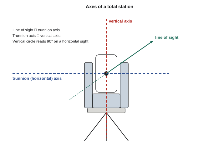
A perfectly adjusted total station has three geometric conditions. The line of sight is perpendicular to the trunnion axis; when it is not, there is collimation (line-of-sight) error. The trunnion axis is perpendicular to the vertical axis; when it is not, there is trunnion-axis (tilting-axis) error. The vertical circle reads exactly 90° when the line of sight is horizontal; when it does not, there is vertical index error. In addition, the vertical axis itself must be truly vertical, which depends on how carefully the instrument is leveled; electronic tilt sensors measure the remaining tilt and correct the angles for it.
The first three errors share a useful property: they change sign when the telescope is transited and the instrument is pointed at the same target on the other face. Averaging face-left and face-right readings therefore removes them. Modern instruments also let the operator measure the errors with a calibration routine and apply corrections automatically, but measuring on both faces remains the standard way to obtain angles of the highest accuracy, and to catch pointing blunders.
| Error | Cause | How it is controlled |
|---|---|---|
| Collimation (line of sight) | Line of sight not perpendicular to trunnion axis | Average both faces; calibrate |
| Trunnion axis | Trunnion axis not perpendicular to vertical axis | Average both faces; matters most on steep sights |
| Vertical index | Vertical circle zero not at the zenith | Average both faces; calibrate |
| Vertical axis tilt | Instrument not perfectly level | Level carefully; dual-axis compensator |
| Centering | Instrument or target not over the mark | Optical or laser plummet; check tribrachs |
| Pointing | Imperfect aim on the target | Repeat pointings; automatic target recognition |
Robotic total stations add servo motors and automatic target recognition, so the instrument can find and follow a prism carried by one person, who controls the instrument from a data collector at the target. Motorized instruments are also used as permanent monitoring stations, measuring prisms on a dam, a bridge or a slope every few minutes and sending alerts if any point moves beyond a set threshold. Reflectorless EDM allows measurement to walls, rock faces and other surfaces that are unsafe or impossible to reach, at shorter ranges and lower accuracy than to a prism.
Prisms and targets matter as much as the instrument. Each prism has a constant, an offset between its optical center and the plumb line that the EDM must apply, and mixing prisms with different constants is a classic cause of a constant distance error of 30 mm or so. Tribrachs, the bases that hold instruments and targets on tripods, have optical or laser plummets that drift out of adjustment and must be checked regularly, because a 2 mm centering error at each end of a 50 m line is worth as much as a 16″ angle error.
Calibration and checks
Instruments are checked in three ways. Field checks, such as the two-peg test, the face-left and face-right comparison and a check shot to a known point at the start and end of every set-up, are done constantly by the crew. Periodic calibration, done by the firm or a service center, measures collimation, trunnion and index errors and the EDM constant and scale. Traceable calibration compares EDM distances with a calibration baseline, a line of pillars whose separations are known very precisely.
In the US, the National Geodetic Survey has published procedures for calibration base lines, and many states maintain them, often through the state department of transportation or a university. State minimum technical standards for land surveys typically require that instruments be maintained and calibrated so that the survey meets its accuracy standard. Coulee Geomatics calibrates its EDMs on a base line each spring before the main field season and keeps the reports on file.
GNSS receivers
A GNSS receiver tracks signals from navigation satellites and measures the range to each of them. Survey-grade receivers track several constellations (GPS, GLONASS, Galileo and BeiDou) on several frequencies, measure the phase of the carrier wave as well as the code, and either work in real time with corrections from a base station or network, or log raw data for later processing. Lesson 6 explains how these measurements become coordinates. As instruments, GNSS receivers are simple to set up, need a clear view of the sky, and are affected by signal reflections (multipath) from nearby buildings, vehicles and water. Antenna heights must be measured to the correct reference point, and antenna calibration models, which describe how the electrical phase center shifts with satellite elevation, are part of every precise processing run.
Scanners, cameras and airborne sensors
A terrestrial laser scanner measures millions of distances and angles per minute by sweeping a laser beam across its surroundings, producing a point cloud. Mobile mapping systems put scanners and cameras on vehicles, and airborne lidar and aerial cameras fly on aircraft and drones (uncrewed aerial vehicles). These instruments combine a ranging or imaging sensor with GNSS and an inertial measurement unit that tracks the sensor's position and orientation many hundreds of times per second. Lessons 7 and 8 cover them in detail. For the engineer, the key point is that their accuracy depends as much on the positioning and orientation system and on calibration of the angles between the sensors as on the sensor itself.
Data collectors and software
Almost every modern instrument is operated through a field controller running survey software. The controller stores the job's coordinate system, control points and design data, prompts the operator through routines, applies corrections and checks tolerances. That brings a real risk: if the coordinate system, geoid model, prism constant or units are wrong in the controller, every measurement will be wrong in the same way, often without obvious symptoms. Coulee Geomatics uses a job set-up checklist, reviewed by a second person, for every new project, and the first observation of each day is a check on a known control point.
| Instrument | Measures | Typical precision | Typical uses |
|---|---|---|---|
| Digital level | Height differences | 0.3–1.5 mm/km | Vertical control, settlement monitoring |
| Total station | Angles and distances | 1–5″; 1–2 mm + 1–2 ppm | Property, engineering and construction surveys |
| GNSS receiver (RTK) | Positions | 1–2 cm horizontal, 2–3 cm vertical | Control, topography, stakeout, machine guidance |
| Terrestrial scanner | Dense 3D points | 2–6 mm at tens of meters | As-built surveys, structures, heritage |
| Airborne lidar | Dense 3D points over large areas | 5–15 cm vertical | Terrain models, floodplains, forestry |
| Aerial camera | Images | Ground sample distance a few cm | Orthophotos, mapping, monitoring |
Reducing a level run
Because leveling is the foundation of vertical control, every geomatics engineer should be able to reduce a level run and judge whether its misclosure is acceptable. The script below reduces a closed loop on the height of instrument method, computes the misclosure, compares it with an allowable value of \(k\sqrt{L}\), where \(L\) is the loop length in kilometers, and distributes the misclosure in proportion to distance.
# Reduce a closed level loop, check the misclosure and adjust in proportion to distance
import math

start = ("BM COULEE 7", 902.417)
# (point, backsight, foresight, distance from previous set-up to this point in m)
obs = [("TP1", 1.623, None, 0),
       ("TP1", 1.402, 0.874, 140),
       ("TP2", 0.987, 2.115, 130),
       ("TP3", 2.311, 1.664, 150),
       ("TP4", 1.205, 0.562, 145),
       ("BM COULEE 7", None, 2.314, 135)]

name0, elev = start
hi = elev + obs[0][1]
points, run = [], 0.0
for pt, bs, fs, d in obs[1:]:
    run += d
    elev = hi - fs
    points.append([pt, elev, run])
    if bs is not None:
        hi = elev + bs

closing = points[-1][1]
mis = closing - start[1]
L_km = run / 1000
allow = 0.012 * math.sqrt(L_km)
print(f"Loop length {run:.0f} m, misclosure {mis * 1000:+.1f} mm, allowable {allow * 1000:.1f} mm")
print("Within tolerance" if abs(mis) <= allow else "Exceeds tolerance: re-run the loop")

for pt, e, dist in points:
    corr = -mis * dist / run
print(f"{pt:12s} raw {e:9.4f} correction {corr * 1000:+5.1f} mm adjusted {e + corr:9.4f}")Loop length 700 m, misclosure -1.0 mm, allowable 10.0 mm Within tolerance TP1 raw 903.1660 correction +0.2 mm adjusted 903.1662 TP2 raw 902.4530 correction +0.4 mm adjusted 902.4534 TP3 raw 901.7760 correction +0.6 mm adjusted 901.7766 TP4 raw 903.5250 correction +0.8 mm adjusted 903.5258 BM COULEE 7 raw 902.4160 correction +1.0 mm adjusted 902.4170
The loop is 700 m long, so the allowable misclosure at 12 mm per square root of kilometer is about 10 mm. The computed misclosure is only 1 mm, so the loop passes and the correction at each point grows in proportion to the distance from the start until it removes the whole misclosure at the closing bench mark. A large misclosure would mean a blunder, such as a misread rod, a moved turning point or a wrong bench mark elevation, and the loop would be re-run rather than adjusted.
Choosing an instrument
Instrument selection starts from the required accuracy, the size of the area and the environment. For a precise settlement monitoring program on a building, a digital level and invar rods are hard to beat. For a property boundary in a treed valley, a total station traverse from GNSS control is often the best combination. For a 40 km pipeline route, GNSS for control with airborne lidar for terrain is usual. For the inside of a pump station, a terrestrial scanner captures everything in an hour. Coulee Geomatics prices jobs by thinking first about the deliverable and its accuracy, then about which combination of instruments meets that accuracy with the least time in the field and the least risk to the crew.
Safety is part of that choice. Instruments that reduce time on the road shoulder, on a rail line or near open water, such as reflectorless total stations, scanners and drones, are often chosen as much for the reduced risk to people as for speed. Every job starts with a hazard assessment, and the instrument plan is part of it.
Common mistakes
MistakeAssuming a fine display resolution means high accuracy.
InsteadJudge accuracy from calibration, checks and misclosures.
MistakeMeasuring angles on one face only when high accuracy is needed.
InsteadAverage face-left and face-right observations to cancel axis errors.
MistakeMixing prisms with different constants.
InsteadRecord and set the prism constant for every target.
MistakeTrusting the controller set-up without checking.
InsteadUse a set-up checklist and observe a known control point first.
Summary and key terms
- Every instrument defines a reference, compares a target with it and records the result.
- Balanced sights cancel level collimation error; the two-peg test measures it.
- Averaging both faces removes collimation, trunnion-axis and vertical index errors.
- Prism constants and tribrach plummets cause constant errors if neglected.
- EDMs are calibrated on baselines with known distances.
- Level loops are checked by misclosure against an allowable value such as \(k\sqrt{L}\).
- Collimation error
- The tilt of a level’s line of sight, or the departure of a total station’s line of sight from perpendicular to the trunnion axis.
- Two-peg test
- A field test that measures the collimation error of a level.
- Trunnion axis
- The horizontal axis about which a total station’s telescope rotates.
- Vertical index error
- The amount by which the vertical circle does not read 90° on a horizontal line.
- Prism constant
- The offset between a prism’s optical center and its plumb line.
- Calibration baseline
- A line of pillars with precisely known separations used to calibrate EDMs.
- Misclosure
- The difference between a computed and a known value at the end of a closed loop or traverse.
Practice problems
Work each problem on paper first, then reveal the answer to check.
A level run of 2.25 km closes with a misclosure of 14 mm. With an allowable value of \(8\sqrt{L}\) mm, does it pass?
Show answer
Allowable is \(8 \times 1.5 = 12\) mm, so it fails.
Why does leveling with equal backsight and foresight distances cancel collimation error?
Show answer
The error is proportional to sight length, so it is the same on both readings and cancels in the difference.
A prism constant is set to 0 mm, but the prism used has a constant of −30 mm. What happens?
Show answer
Every distance is about 30 mm too long.
Name three errors removed by averaging both faces.
Show answer
Collimation, trunnion-axis and vertical index error.
What is the lateral error of a point 50 m away caused by a 2 mm centering error at the instrument?
Show answer
Up to 2 mm, equivalent to an angle error of about 8″ at 50 m.
Lesson quiz · 5 questions
Score 60% or more to complete this lesson.
Create a free account to save your progress, take quizzes and earn a certificate.