
GAS-320 · Lesson 9 of 12 · 24 min
Multiple appliances on common vents
▶ Video coming soon A video version of this lesson is on the way.
On Friday, October 23, Maureen and Grant met Gerald Moss, the owner of a 1962 three-story walk-up with twenty-four apartments on a side street in the University District of Columbus. The building's tenants had complained all summer that the hot water ran out in the evenings. Gerald had a plan and a quote from a handyman: add a third water heater beside the two in the basement and connect its vent into the same chimney. "There's a big hole in the chimney already," he said. "How hard can it be?" Maureen asked to see the boiler room before answering. "The chimney already carries three appliances' worth of flue gas in winter," she said. "Whether it can carry a fourth isn't a matter of whether the pipe fits in the hole."
This lesson explains how several Category I appliances share one vent or chimney: why common venting works, the rules for connectors and their entry into the common vent, how a common vent is sized from the combined input using the code's tables, why some appliances can never share a vent, and how to test a common vent system. All the sizing tables in this lesson are SAMPLE tables made up for illustration; real work uses the tables of NFPA 54 or of the vent maker.
Why appliances share vents
In older commercial and apartment buildings it was normal to run every atmospheric appliance into one chimney: the boiler, the water heaters, sometimes an incinerator or a dryer. Common venting saves the cost and space of separate vents, and a common vent carrying several appliances' flue gas is warmer and draws better than separate cold vents would. The code allows it for Category I appliances, those whose vents operate under negative pressure and whose flue gas is hot enough not to condense in the vent: draft-hood appliances and fan-assisted non-condensing appliances. They can share a vent because each one's flue gas rises by buoyancy and none pushes its gas into the vent under pressure.
Common venting has limits. The common vent must be large enough to carry all the appliances' flue gas when they all fire together, but not so large that one small appliance firing alone sends cool, slow flue gas into a big cold vent where it condenses and drafts poorly. Each appliance's vent connector, the pipe from its draft hood or flue outlet to the common vent, must have enough rise and diameter to start its flue gas moving. And the connectors must join the common vent in a way that does not let one appliance's gas flow back down another's connector.
Rules for vent connectors
The codes and the vent makers' instructions set out the details; these are the principles behind them.
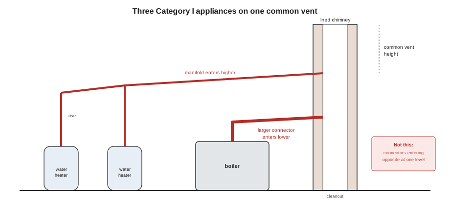
- Each connector must rise continuously from the appliance toward the common vent, with no dips, and the more rise it has before it turns horizontal, the more flue gas it can carry. A connector's capacity in the tables depends on its diameter and its rise.
- Horizontal runs are limited in length for their diameter, because a long horizontal connector cools the gas and loses draft.
- Connectors must enter the common vent at different levels, or join through a properly made manifold or tee designed for the purpose, never directly opposite each other at the same height, where one appliance's flue gas can blow across into the other's connector.
- Where connectors enter at different heights, the smaller connector generally enters at the higher level, so that the larger appliance's flow does not overwhelm it.
- A connector must not be smaller than the appliance's flue outlet, and must not pass through floors, ceilings or walls except as the code allows.
- Each connector must be readily accessible for inspection and must be secured so that it cannot separate; GAS-110's Barton Street incident began with a disconnected connector.
Appliances that must not share
Some appliances must never be connected into a common natural draft vent. Category III and IV appliances, whose vents run under positive pressure, would push their flue gas out of the other appliances' draft hoods into the building. Category II and IV condensing appliances produce flue gas too cool for a Category I vent and would fill it with condensate. A power-vented appliance, an appliance with a mechanical draft fan that pressurizes its vent, may join a common vent only if the vent is a system designed and listed for that. Some condensing boilers and water heaters may share a vent with each other, but only through a common vent system that their maker specifically lists for it, with the maker's components and limits. And an appliance that the code requires to have a separate vent, such as some incinerators and solid-fuel appliances, cannot share with gas appliances at all.
Sizing a common vent
A common vent is sized from the tables in chapter 13 of NFPA 54, or from the vent maker's tables, which give the capacity of a common vent of a given diameter, height and material for the kinds of appliances attached, for example two draft-hood appliances or one fan-assisted and one draft-hood. The height used is the distance from the highest draft hood or flue outlet to the top of the vent. The tables also give the capacity of each connector for its diameter and rise. The common vent must be at least as large as the largest connector, and its capacity must be at least the combined input of all the appliances that can fire together. The tables also have a minimum: a common vent that is too large for the appliances can fail to draft, especially when only the smallest appliance fires.
| Common vent diameter | Height 30 ft | Height 40 ft | Height 50 ft |
|---|---|---|---|
| 8 in. | 650,000 Btu/h | 700,000 Btu/h | 750,000 Btu/h |
| 10 in. | 1,100,000 Btu/h | 1,200,000 Btu/h | 1,300,000 Btu/h |
| 12 in. | 1,600,000 Btu/h | 1,750,000 Btu/h | 1,875,000 Btu/h |
| Connector diameter | Rise 1 ft | Rise 2 ft | Rise 3 ft |
|---|---|---|---|
| 4 in. | 160,000 Btu/h | 180,000 Btu/h | 195,000 Btu/h |
| 5 in. | 250,000 Btu/h | 280,000 Btu/h | 300,000 Btu/h |
| 6 in. | 350,000 Btu/h | 400,000 Btu/h | 430,000 Btu/h |
Worked problem
Can the chimney take a fourth appliance?
The University District chimney has a 10 in. liner. The highest draft hood is 50 ft below the top. Attached now are a draft-hood boiler of 800,000 Btu/h and two draft-hood water heaters of 199,900 Btu/h each. Gerald wants to add a third water heater of 199,900 Btu/h. Using the SAMPLE table, check the common vent now and with the new heater.
Show solution
- Combined input now:
- \[800{,}000 + 2 \times 199{,}900 = 1{,}199{,}800 \text{ Btu/h}\]
- SAMPLE capacity, 10 in. at 50 ft:
- 1,300,000 Btu/h, so 1,199,800 Btu/h fits.
- Combined input with a third heater:
- \[1{,}199{,}800 + 199{,}900 = 1{,}399{,}700 \text{ Btu/h} > 1{,}300{,}000 \text{ Btu/h}\]
Answer: The chimney is adequate for the three appliances it serves now, with a small margin, but adding a fourth puts it over its capacity. On a cold evening, with the boiler firing and all three water heaters recovering, it would not carry the flue gas, and the appliances would spill. The answer to Gerald's plan is no.
Worked problem
Would the handyman's connector have worked?
The handyman planned a 4 in. connector for the new 199,900 Btu/h heater, with 1 ft of rise before it turned horizontal to the chimney. Using the SAMPLE connector table, check it, and find the smallest diameter that would carry the heater with that rise.
Show solution
- SAMPLE capacity, 4 in. with 1 ft rise:
- 160,000 Btu/h < 199,900 Btu/h
- SAMPLE capacity, 5 in. with 1 ft rise:
- 250,000 Btu/h ≥ 199,900 Btu/h
Answer: Even if the chimney had had room, the planned connector would have been too small for the heater with so little rise. It would have needed the next size up, or more rise. A pipe that fits the hole and the draft hood is not necessarily a pipe that carries the flue gas.
What Maureen found in the boiler room
The inspection turned up two more problems with the existing system. First, the two water heaters' connectors entered the chimney directly opposite each other, at the same height, through two holes knocked in the masonry from either side. With both heaters firing, Maureen's smoke test at one heater's draft hood showed the smoke being pushed out, not drawn in: the other heater's flue gas was blowing across the chimney into it. Second, the breeching from the boiler had a section that sagged between hangers, collecting rust scale. With the boiler, both water heaters and the building's laundry dryers all running, which the tenants did every evening, Maureen measured the draft at each draft hood and ran a spillage test at each. The boiler drafted well. One water heater spilled for more than a minute before drafting, and its connector, the one blown into by its neighbor, read 45 ppm of carbon monoxide at its draft hood.
Maureen explained the findings to Gerald with the SAMPLE numbers and her readings. Her recommendations, in writing, were: rearrange the two existing water heaters' connectors into a properly made manifold entering the chimney at one point, at a different level from the boiler's breeching; rehang the boiler's breeching with proper hangers; and, rather than adding a third atmospheric heater to the chimney, install the extra water heating as a condensing, direct-vent water heater venting through the wall with its own intake and exhaust, which does not touch the chimney at all. She also suggested checking the hot water demand: the tenants' evening complaints might be partly due to the existing heaters' scaled tanks, which would be cheaper to fix than to add capacity to.
If an appliance is removed
The reverse problem is just as important. When one appliance on a common vent is removed or replaced with a direct-vent model, the remaining appliances are left on a vent sized for more flue gas than they now produce. The vent may be too large for them, especially in cold weather, and the code requires the remaining system to be checked and, if necessary, resized, often with a new liner. GAS-230 called these orphaned appliances. Whenever you change any appliance on a common vent, you have changed the whole system and must check it as a whole.
Testing a common vent system
A common vent is tested in the conditions that stress it most, the same principle GAS-230 used for a single appliance: with the building's exhaust fans, dryers and other air-moving equipment in the worst combination for the room the appliances are in. Then test each appliance firing alone, beginning with the smallest, because a small appliance firing alone into a large cold vent is the most likely to spill; then fire them together and test each again. Check draft at each draft hood or flue outlet, look for spillage with smoke or a mirror, and measure carbon monoxide in the flue gas and around each appliance. Record the results for each appliance in each condition.
| Test condition | What it checks |
|---|---|
| Smallest appliance firing alone, cold vent | Whether the vent is too large for it and drafts poorly |
| All appliances firing together | Whether the vent carries the combined flue gas |
| Exhaust fans and dryers running | Whether building depressurization overcomes the draft |
| Each draft hood with smoke | Spillage, and cross-flow from a neighboring connector |
| Flue gas and ambient carbon monoxide | Combustion and spillage of combustion products |
Larger common vent systems
In bigger buildings you will meet common vent arrangements more elaborate than a basement chimney. Multistorey venting runs one vertical common vent up through the floors of an apartment or office building, with an appliance such as a water heater or furnace on each floor connected into it; the code and the vent maker set strict rules for the connectors, the vent's size at each floor and the ventilation of each appliance space, and a change on one floor affects every floor above. Common breechings in boiler rooms collect the flue gas of several boilers into one horizontal header that rises into a stack; with power-burner boilers, the breeching and stack are often designed by an engineer, and they may have a barometric damper, a weighted flap that admits room air to steady the draft, or a draft control system with a fan and sensors that holds the draft at each boiler within a set range. Some modern plants use listed common venting systems for condensing boilers, with backflow preventers on each boiler so that flue gas cannot enter an idle boiler. In every case the principle is the same as in Gerald's basement: the vent serves the system, and no single appliance can be changed without checking the whole.
Common mistakes
MistakeAdding an appliance to a common vent because the connector fits.
InsteadSize the common vent for the new combined input and check the connector's capacity and rise.
MistakeLetting connectors enter the chimney opposite each other at the same level.
InsteadEnter at different levels or through a proper manifold.
MistakeConnecting a power-vented or condensing appliance into a natural draft common vent.
InsteadOnly Category I appliances may share a natural draft vent, unless a maker lists a common system.
MistakeRemoving one appliance from a common vent and leaving the rest unchanged.
InsteadRecheck and resize the vent for the appliances that remain.
MistakeTesting a common vent with only the largest appliance firing.
InsteadTest the smallest appliance alone, all together, and with exhaust equipment running.
Summary and key terms
- Category I appliances, draft-hood and fan-assisted non-condensing, may share a common vent because their vents run under negative pressure and their flue gas stays hot.
- Each connector needs enough diameter and rise, limited horizontal length and a secure, accessible joint, and connectors must enter the common vent at different levels or through a proper manifold, never opposite each other.
- A common vent is sized from the code's or the maker's tables from its height, diameter and material and the combined input of the appliances that fire together, with a minimum as well as a maximum.
- Category III and IV and condensing appliances must not join a natural draft common vent unless a listed common system is used.
- Adding or removing any appliance changes the whole system, which must be rechecked, and testing covers the smallest appliance alone, all together and the worst-case building pressure.
- Common vent
- A vent or chimney serving two or more appliances.
- Vent connector
- The pipe from an appliance's draft hood or flue outlet to the vent or chimney.
- Connector rise
- The vertical distance a connector climbs before running horizontally.
- Combined input
- The total input of all appliances on a common vent that can fire together.
- Category I appliance
- An appliance whose vent runs under negative pressure with flue gas too hot to condense.
- Manifold
- A section of vent that collects several connectors before entering the common vent.
- Orphaned appliance
- An appliance left alone on a vent sized for more appliances.
Practice problems
Work each problem on paper first, then reveal the answer to check.
Why may Category I appliances share a vent while Category IV appliances may not?
Show answer
Category I vents run under negative pressure with hot flue gas; Category IV vents are pressurized and condensing.
Why must connectors not enter a common vent opposite each other at the same level?
Show answer
One appliance's flue gas can blow across into the other's connector and out of its draft hood.
Using the SAMPLE table, can a 10 in. common vent 40 ft high carry 1,150,000 Btu/h?
Show answer
Yes: its SAMPLE capacity is 1,200,000 Btu/h.
Which appliance is the most likely to spill when tested alone on a common vent?
Show answer
The smallest, firing alone into a large cold vent.
What did Maureen recommend instead of a third atmospheric water heater?
Show answer
A condensing, direct-vent water heater vented separately through the wall.
Lesson quiz · 5 questions
Score 60% or more to complete this lesson.
Create a free account to save your progress, take quizzes and earn a certificate.