
FAT-220 · Lesson 8 of 12 · 21 min
Interconnection with other systems
On a Thursday afternoon, the north wing's job meeting fills the site trailer: the elevator installer, the mechanical contractor, the door hardware supplier, Luis from the sprinkler crew, the building automation programmer and, for Bramwell, Gerry and Sasha. Ravi has brought a single table: every input on the north wing's fire alarm, every output, and what each input must make happen. 'When a smoke detector in the third-floor elevator lobby goes off,' he says, 'five different trades have to have done their part right for the right thing to happen.' Very little of what a fire alarm does to protect people happens inside the fire alarm itself. It recalls elevators, shuts down or starts fans, closes doors, releases locks and tells other systems what is going on. This lesson covers how those interconnections are installed, the rules that govern them, and how the trades share the work.
Emergency control functions
NFPA 72, Chapter 21, calls these emergency control functions and sets requirements for the interfaces that perform them: elevator recall and shutdown, fan control and smoke control, door and shutter release, electrically locked door release, and others. The functions themselves are required by the building code, NFPA 101 and the standards for the systems concerned, such as ASME A17.1 for elevators. The fire alarm's job is to provide a reliable signal; the other system's job is to respond to it correctly. The interface between the two is where most problems happen.
The interface is usually a control relay or control module in the fire alarm system, whose contacts switch a circuit in the other system. The fire alarm installer is responsible for the relay and the wiring to it; the other trade is responsible for its equipment and for connecting to the relay's contacts at the point the design shows. The contact rating of the relay must suit the circuit it switches: a relay rated for low-voltage signals can't switch a motor starter coil directly unless its rating allows.
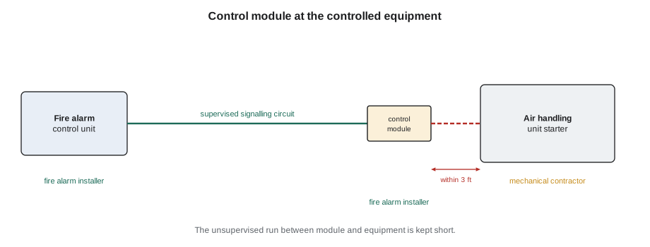
NFPA 72 requires the relay or other device that performs the control function to be located within 3 feet of the controlled circuit or appliance, unless the wiring between them is monitored for integrity or protected, so that a fault in an unsupervised run can't silently disable the function. The wiring from the fire alarm to the relay is supervised.
Elevator recall
Elevators are recalled under ASME A17.1 when smoke is detected in an elevator lobby, the machine room or the hoistway. NFPA 72 sets the interface: a detector in the lobby on the designated recall level sends the elevators to the alternate level; a detector anywhere else sends them to the designated level; and a detector in the machine room, the hoistway or other specified locations also causes the fire hat indicator in the cars to flash. The fire alarm provides separate signals for these cases, usually through separate relays, and the elevator installer connects them to the elevator controller. The detectors that initiate recall are part of the fire alarm system.
Where the elevator machine room or hoistway has sprinklers, the elevator code generally requires the elevator's power to be shut off before the sprinkler water reaches the equipment, using a shunt trip on the elevator's power supply. The shunt trip is initiated by heat detectors placed near the sprinklers, with a lower temperature rating so that they operate first. The heat detectors are installed close to each sprinkler head, as the code requires, and their signal operates a relay that trips the elevator's main breaker. The fire alarm also monitors the shunt trip's control voltage, so that a loss of that voltage is reported.
Recall is a function where the trades must coordinate in detail. The elevator installer needs to know which relay is which, the fire alarm installer needs to know which terminals in the elevator controller to land on, and both need to know the designated and alternate floors. The test is done with both trades present, floor by floor, during verification or acceptance testing.
Fans, dampers and smoke control
Air handling systems can spread smoke through a building, so many designs shut them down or reconfigure them when smoke is detected. A duct detector in an air handling unit, or an area detector the design assigns, operates a control module that stops the fan or closes smoke dampers. In buildings with dedicated smoke control systems, such as stair pressurization in high buildings or smoke exhaust in atriums, the fire alarm starts the smoke control fans and opens or closes dampers in a programmed sequence.
Smoke control systems are designed by the mechanical engineer, and the sequence of operation is written jointly with the fire alarm designer. The fire alarm installer programs the outputs and wires the control modules; the mechanical and controls contractors install the fans, dampers and their controls. Where the building has a firefighter smoke control panel, the fire alarm may also provide status indication for it. Each fan and damper's response is checked during commissioning.
Many building automation systems now receive fire alarm information over a network interface rather than through relays. Such an interface can report status to the building automation system, but life-safety control functions, such as stopping a fan for smoke control, are generally still performed through listed fire alarm relays or listed interfaces, not through ordinary building automation programming, unless the equipment is listed for that purpose. Sasha should treat a network link as a reporting channel unless the design says otherwise.
Doors and locks
Fire doors in corridors and stairs are often held open for convenience by magnetic door holders, which release when the fire alarm operates or the power fails, so that the doors close and contain smoke. Door holders are powered by the fire alarm or a separate supply, as the design shows, and the fire alarm removes their power through a relay. Doors with closers that have built-in smoke detectors may act on their own, but the design usually ties them to the fire alarm as well.
Electrically locked egress doors are allowed by the IBC and NFPA 101 only under strict conditions, one of which is that they unlock when the fire alarm or sprinkler system operates and on power failure. The fire alarm provides the release signal through a relay or by removing power to the locks' supply, and the arrangement must be fail-safe: any failure must leave the doors unlocked. In the north wing, the doors to the secure psychiatric unit use delayed-egress locks under the health care provisions of the codes, released by the fire alarm.
The door hardware supplier and the fire alarm installer agree where the release signal enters the lock's power supply. The release is tested at every door during verification or acceptance testing, because a locked egress door that doesn't release is among the most dangerous failures a fire alarm can have.
Sprinklers and other suppression systems
The fire alarm monitors sprinkler systems through waterflow and valve supervisory switches, as Lesson 4 covered, and also monitors other conditions the sprinkler standard requires, such as low air pressure on dry systems, fire pump status, and low water level or temperature in tanks. Each of these is a supervisory signal, distinct from an alarm, except waterflow, which is an alarm. Fire pump monitoring, for a pump like Riverlight Tower's, covers the pump running, loss of power or phase reversal, and the controller's status, as the fire pump standard specifies.
Other suppression systems, such as kitchen hood systems, clean-agent systems in computer rooms and pre-action sprinkler systems, are connected so that their operation is reported to the fire alarm and, where the design calls for it, the fire alarm sounds the building alarm. Releasing a suppression system from the fire alarm, as for a pre-action or clean-agent system, is only done with a control unit listed for releasing service, using the releasing standard's requirements, and with the suppression contractor's coordination.
The input and output matrix
All of these interconnections are captured in the design's sequence of operation, usually as a matrix with inputs down one side and outputs across the top, and a mark wherever an input must cause an output. FAT-210 covers how the matrix is programmed. For installation, the matrix is the checklist: every output in the matrix needs a relay or module, installed and wired to the right equipment, and every input-output pair needs to be tested.
# Interface check: every output in the matrix has an installed module near its equipment
max_distance = 3   # ft from module to controlled circuit, unless the wiring is supervised
outputs = [
    ("recall primary",   "elevator ctrl L1", True,  2, False),
    ("recall alternate", "elevator ctrl L1", True,  2, False),
    ("fire hat",         "elevator ctrl L1", True,  2, False),
    ("AHU-N1 stop",      "starter AHU-N1",   True,  15, False),
    ("door holders L3",  "DH supply L3",     False, 0,    False),
    ("mag locks psych",  "lock PSU 4N",      True,  30, True),
]
for name, equip, installed, dist, supervised in outputs:
    issues = []
    if not installed: issues.append("module not installed")
    elif dist > max_distance and not supervised: issues.append(f"{dist} ft away, wiring not supervised")
print(f"{name:17s} -> {equip:17s}", "OK" if not issues else "; ".join(issues))recall primary -> elevator ctrl L1 OK recall alternate -> elevator ctrl L1 OK fire hat -> elevator ctrl L1 OK AHU-N1 stop -> starter AHU-N1 15 ft away, wiring not supervised door holders L3 -> DH supply L3 module not installed mag locks psych -> lock PSU 4N OK
The check finds two issues: the door holder module for the third floor hasn't been installed yet, and the AHU-N1 stop module is too far from the starter without supervised wiring. The fix for the second is to move the module into the starter's enclosure area, as the design intended, rather than leaving it in the electrical room.
Coordinating the trades
Interfaces cross trade boundaries, so they need clear responsibilities in writing. On the north wing, Ravi's table lists, for each interface: the fire alarm device and its address, the controlled equipment and its location, which trade installs each part, the point of connection, the expected response and the test method. Each trade signs off its part. When the functions are tested, all the trades whose equipment is involved are present, because a recall test that fails could be the relay, the wiring, the elevator controller's programming or the elevator itself, and only the trades together can find out which.
Worked problem
The third-floor elevator lobby
During pre-testing, Sasha activates the smoke detector in the north wing's third-floor elevator lobby. The elevators go to the main floor as they should, but the fire hat in the cars flashes, which it shouldn't for a lobby detector. What could be wrong, and how is it found?
Show solution
- Check the program: the lobby detector may have been mapped to the fire hat relay as well as the primary recall relay. Compare the panel's program with the matrix.
- Check the wiring: the primary recall and fire hat relays may have been landed on the wrong terminals in the elevator controller, or swapped. Check the relay outputs with a meter while activating each detector type.
- Check the elevator controller's configuration with the elevator installer: its inputs may be configured differently from what the drawings assume.
- Correct the fault, then retest every recall case: designated floor lobby, other lobbies, machine room and hoistway.
Answer: With the trades together, the cause is found in minutes: the two relays' wires had been swapped at the elevator controller's terminal strip, and moving them back fixes the fault.
Monitoring other systems' status
Not every interconnection is a control. Many are status monitoring: the fire alarm watches another system and reports its condition. Fire pumps, generators serving life safety loads, smoke control fans and kitchen hood systems are common examples. A monitor module wired to a status contact in the other equipment reports alarm, supervisory or trouble as the design assigns. The contact is chosen so that a broken wire is reported: the module's end-of-line device is at the contact, not at the module, so the whole run is supervised.
Status monitoring catches problems before they matter. When the north wing's generator transfer switch was tested, the fire alarm reported the generator running as a supervisory signal, just as the design intended, and the hospital's maintenance staff could see the transfer happen at the annunciator.
Common mistakes
MistakeMounting a control relay far from the equipment with unsupervised wiring.
InsteadMount it close to the controlled equipment, or supervise the wiring.
MistakeUsing a relay whose contacts aren't rated for the controlled circuit.
InsteadCheck the contact rating against the load.
MistakeTreating a building automation network link as a life-safety control path.
InsteadUse listed fire alarm relays or interfaces for control functions.
MistakeReleasing a suppression system from an ordinary control unit.
InsteadOnly control units listed for releasing service release suppression systems.
MistakeTesting an interface without the other trade present.
InsteadTest interfaces with every trade whose equipment is involved.
Summary and key terms
- The fire alarm controls other systems through relays and modules.
- Control devices are placed close to the equipment they control, with supervised wiring to the fire alarm.
- Elevator recall has separate signals for different detector locations.
- Fans, dampers and smoke control follow a jointly written sequence of operation.
- Door holders and electromagnetic locks must release on alarm and fail safe.
- Suppression systems are monitored, and released only by listed releasing panels.
- The input and output matrix is the installation checklist.
- Emergency control function
- A function the fire alarm performs through another system, such as elevator recall.
- Control module
- An addressable device whose contacts control another system.
- Elevator recall
- Sending elevators to a designated level when smoke is detected.
- Shunt trip
- A breaker trip that removes power to elevator equipment before sprinklers discharge.
- Fail-safe
- Arranged so that a failure leaves the safe condition, such as doors unlocked.
- Releasing service
- Use of a control unit to discharge a suppression system.
Practice problems
Work each problem on paper first, then reveal the answer to check.
Who is responsible for the elevator controller's response to a recall signal?
Show answer
The elevator installer; the fire alarm provides the signal.
Why do elevator shunt-trip heat detectors have a lower rating than the nearby sprinklers?
Show answer
So that power is removed before the sprinklers discharge water.
What must happen to electromagnetic egress locks on a fire alarm signal?
Show answer
They must release.
Why must a door lock release arrangement be fail-safe?
Show answer
So that any failure leaves the doors unlocked.
What does the input and output matrix give the installer?
Show answer
A checklist of every interface to install and test.
Lesson quiz · 5 questions
Score 60% or more to complete this lesson.
Create a free account to save your progress, take quizzes and earn a certificate.