
FAT-220 · Lesson 6 of 12 · 21 min
Wiring, pathways and circuit installation rules
The north wing's riser has gone in, and Gerry walks the third floor with Sasha before the ceilings close, looking up at the cable. Most of it is neatly supported on J-hooks screwed to the deck. In one corridor, though, the electrician's crew has run the outgoing and return legs of a Class A signaling circuit side by side in the same J-hooks, and in another, a bundle of fire alarm cable is lying across the top of a duct. 'The outgoing and return legs are supposed to take different routes,' Gerry says, 'or a single hit takes out both.' FAT-130 covered cable types, wiring methods and survivability, and FAT-210 covers circuit classes. This lesson pulls the installation rules together: how pathways are routed, supported, separated, terminated, identified and tested, as the installation standard requires them to be.
The wiring rules come from two places
The wiring of a fire alarm system follows both NFPA 70, Article 760, and NFPA 72, Chapter 12. The electrical code sets the cable types, wiring methods, separation from other circuits and the supply. NFPA 72 adds the fire alarm rules: pathway classes, how Class A and Class X pathways are routed, pathway survivability levels, how wiring is monitored for integrity, and how it is tested before the system is placed in service. The local electrical inspector enforces the electrical code; the fire alarm acceptance test checks the NFPA 72 rules. An installation must satisfy both.
On most projects, an electrical contractor pulls the cable and a fire alarm contractor terminates and programs the system, or the fire alarm contractor does it all. Either way, the person pulling the cable must know the fire alarm rules, because routing mistakes like the one Gerry found are almost impossible to fix once the ceilings are closed.
Pathway class on the drawings
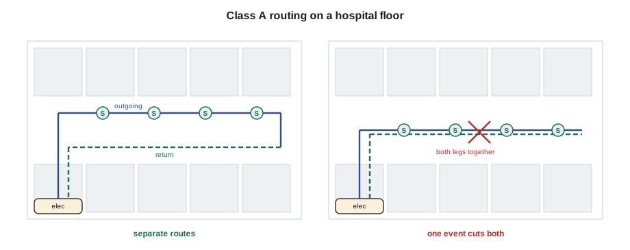
The designer decides the class of each circuit, as FAT-210 describes, and shows it on the drawings. The class affects how the circuit is installed. A Class B circuit runs out from the panel and ends at its end-of-line device. A Class A circuit runs out and back, so that a single open doesn't stop it from working, and its two legs must be routed apart so that a single event doesn't damage both. Class X, used in NFPA 72 for circuits that must keep working through an open, a short or a ground, has the same routing requirement. Installing a Class A circuit with its legs together in one conduit gives the cost of Class A with the reliability of Class B.
NFPA 72 requires the outgoing and return conductors of Class A and Class X pathways to be routed separately, with limited exceptions such as a short vertical drop to a single device and runs within a single room up to a set size. The required separation depends on the edition and the pathway, and the designer shows the two routes on the drawings so that the installer can follow them.
Supporting the cable
Fire alarm cable is supported by the building structure, not by other systems. It must not be tied to sprinkler pipes, ductwork, conduit belonging to other systems, ceiling grid hanger wires or the ceiling grid itself, and it must not lie on a suspended ceiling or on top of ducts or light fixtures. Supports are spaced so that the cable doesn't sag excessively, using hardware listed or suitable for the cable, such as J-hooks or bridle rings. The supports must not damage the cable: overtightened cable ties can crush it, and sharp edges can cut through the jacket as the building moves.
In ceilings used as air plenums, the cable and its supports must be suitable for the plenum, as FAT-130 covered. In exposed locations where cable could be damaged, such as low on a warehouse wall or in a parking structure, it is run in conduit. Circuit integrity cable, where used for survivability, is supported exactly as its listing describes, with the specified supports at the specified spacing, because the fire rating depends on the whole assembly.
# Support spacing and support-method check along a cable run (illustrative limits)
max_spacing = 5          # ft between supports (check the electrical code and maker)
supports = [0, 4, 8, 14, 18, 22]   # positions along the run, ft
methods = ["J-hook to deck", "J-hook to deck", "tied to sprinkler pipe", "J-hook to deck", "J-hook to deck", "J-hook to deck"]
for i in range(1, len(supports)):
    gap = supports[i] - supports[i - 1]
    flag = "OK" if gap <= max_spacing else "too far apart"
    bad = "" if "deck" in methods[i] else "  <- not allowed: support from structure only"
print(f"support {i}: gap {gap:>5} ft {flag}{bad}")support 1: gap 4 ft OK support 2: gap 4 ft OK <- not allowed: support from structure only support 3: gap 6 ft too far apart support 4: gap 4 ft OK support 5: gap 4 ft OK
Separation from other systems
Fire alarm circuits are kept separate from power, lighting and other systems' circuits, as the electrical code requires, and power-limited fire alarm circuits are kept separate from non-power-limited circuits. In practice, this means fire alarm cable doesn't share a conduit or box with building power, and where it enters a box or cabinet that also contains power wiring, such as the control unit itself, it follows the routing and barriers the maker shows. Where a fire alarm cable must share a cable tray or a pathway with communication cables, the electrical code's conditions for doing so are followed.
Separation also protects the system from people working on other systems. Fire alarm junction boxes are identified, and fire alarm cable is distinguishable, so that an electrician replacing a light fixture doesn't cut or reuse a fire alarm conductor. On the north wing, Ravi's specification requires red-painted junction box covers labeled 'FIRE ALARM' and red-jacketed cable, which goes beyond the minimum but makes the system obvious.
Boxes, splices and terminations
Fire alarm circuits are terminated on the devices' terminals, entering and leaving on separate terminals where the device has them, so that removing a device opens the circuit and causes a trouble. Looping a conductor under a single terminal screw, so that the wire continues past the device unbroken, defeats this supervision: the device could be removed and the circuit would not report it. The installation standard forbids it on supervised circuits.
Splices are kept to a minimum and are made only in accessible junction boxes, using connectors listed for the conductors. Each splice is a point where corrosion, a loose connection or a nick in the conductor can cause a fault months later, so many specifications forbid splices in signaling line circuits altogether, except in terminal cabinets. Where splices are needed, their locations are recorded on the as-built drawings, which NFPA 72-2025 now also asks for on shop drawings, so that a technician hunting a fault knows where to look.
Conductors are identified at every termination point with the circuit name or number, and at the control unit each field circuit is labeled. A consistent color scheme for conductors, such as red for positive and black for negative on notification circuits, helps prevent reversed polarity, which on a polarized notification circuit leaves the appliances dark in alarm while the circuit looks normal in standby.
Circuits that leave the building
Some fire alarm circuits run between buildings, such as Eastview's network link to the north wing's separate entrance canopy, or to an outbuilding. Circuits outside the building need cable listed for the location, such as cable rated for wet or direct-burial use, and protection against lightning and power-line surges where they enter each building, using listed surge protective devices as the maker and the electrical code require. Outdoor circuits are also more exposed to damage, so many designers use fiber-optic links between buildings, which are immune to surges and ground potential differences.
Wiring in wet or corrosive locations, such as parking structures, cold storage or areas washed down for cleaning, needs boxes, devices and cable suited to the conditions. FAT-130's ground fault in the Eastview parking structure was caused by water collecting in a box; a weatherproof box with a drain, mounted so that water doesn't run into it along the conduit, would have prevented it.
Testing the wiring before devices are connected
NFPA 72 requires field wiring to be tested for stray voltage, ground faults, short circuits and loop resistance before the system is placed in service, and the results to be recorded. The installer tests each circuit with the devices disconnected, using an insulation resistance tester at a voltage the equipment can withstand, and records the results. The acceptance test later checks the system as a whole, but faults found at this stage are far cheaper to fix.
The tests also catch installation mistakes that wouldn't show as electrical faults later. Crossed conductors between two circuits, a missing conductor in a Class A return, or a circuit that runs to the wrong floor all show up when each circuit is checked from end to end against the drawings. Gerry's practice is to ring out every circuit with a partner, one person at each end, before any device is connected.
# Pre-energizing wiring test record: flag circuits that need attention (illustrative limits)
min_insulation = 20      # megohms, conductor to conductor and to ground
max_loop = {"SLC": 40, "NAC": 6}   # ohms, from the design
tests = [("SLC-N1", "SLC", 8.4, ">500", ">500"),
         ("SLC-N2", "SLC", 41.0, ">500", ">500"),
         ("NAC-N2-1", "NAC", 5.1, ">500", "0.8"),
         ("NAC-N2-2", "NAC", 4.7, ">500", ">500")]
for name, kind, loop, ins_cc, ins_g in tests:
    def mohm(t): return 1e9 if t.startswith(">") else float(t)
    notes = []
    if loop > max_loop[kind]: notes.append(f"loop {loop} ohm > {max_loop[kind]}")
    if min(mohm(ins_cc), mohm(ins_g)) < min_insulation: notes.append("low insulation: look for a ground")
print(f"{name:9s}", "pass" if not notes else "; ".join(notes))SLC-N1 pass SLC-N2 loop 41.0 ohm > 40 NAC-N2-1 low insulation: look for a ground NAC-N2-2 pass
In the sample record, SLC-N2's loop resistance is higher than the design allows, which points to a long run, a wrong conductor size or a poor splice. NAC-N2-1's low insulation to ground points to a nicked jacket or a wet box. Both are found and fixed before any devices go on.
Worked problem
The third-floor walk
During Gerry's walk of the north wing's third floor, he finds a Class A circuit with both legs in the same J-hooks, a fire alarm bundle lying on top of a duct, two splices in a ceiling with no box, and a device where the conductors loop under a single terminal. What has to happen?
Show solution
- The Class A legs: reroute the return leg along the separate route the drawings show; if the drawings don't show one, the designer must provide it before the ceiling closes.
- The bundle on the duct: support it from the structure on its own supports.
- The loose splices: remake them in an accessible junction box with listed connectors, or replace the cable to eliminate them, and record any splice location on the as-built drawings.
- The looped terminal: cut and terminate the conductors on separate in and out terminals so that removing the device causes a trouble.
- Ring out and insulation-test the affected circuits again, and record the results.
Answer: Each defect is something the verification would find, but finding it before the ceilings close turns a costly repair into an afternoon's work.
Penetrations and firestopping
Every time fire alarm cable passes through a fire-rated wall, floor or ceiling, the hole it passes through must be sealed with a listed firestop system that restores the rating. The firestop system is chosen for the specific penetration: the type of wall or floor, the size of the opening, the type and amount of cable, and whether the cable is in a sleeve or conduit. Each listed system specifies the materials and how they are installed, and only those materials, installed as specified, give the rating. Stuffing mineral wool into a gap or squirting ordinary caulk around a cable is not a firestop system.
On many projects, a specialist firestop contractor seals the penetrations, but the fire alarm installer must still leave openings that a listed system can seal, and must not add cables to a sealed penetration without having it resealed. On the north wing, each penetration through a rated wall is labeled with the firestop system used, and the label is photographed for the records. When Sasha's crew needs to add a cable through a sealed sleeve, the firestop contractor removes and replaces the seal, and the label is updated.
Penetrations through smoke barriers in a hospital need the same care, because a gap lets smoke through into the compartment where patients are being protected. The fire inspector will look at these closely, and so will the hospital's own life safety staff, who inspect barriers regularly.
Common mistakes
MistakeRunning Class A outgoing and return legs together.
InsteadRoute the legs separately, as the drawings show.
MistakeSupporting cable from sprinkler pipes, ducts or ceiling grid wires.
InsteadSupport fire alarm cable from the structure.
MistakeLooping a conductor under one terminal.
InsteadTerminate on separate in and out terminals so the circuit stays supervised.
MistakeSplicing above a ceiling without a box.
InsteadSplice only in accessible boxes, and record the location.
MistakeConnecting devices before testing the wiring.
InsteadTest continuity, shorts and grounds first, and record the results.
Summary and key terms
- Fire alarm wiring must satisfy both the electrical code and the fire alarm standard.
- Class A and similar pathways need separately routed outgoing and return legs.
- Cable is supported by the structure, not by other systems.
- Fire alarm circuits are separated from other systems and identified.
- Conductors terminate on separate in and out terminals; splices are minimal and in boxes.
- Circuits leaving the building need suitable cable and surge protection.
- Field wiring is tested before devices are connected.
- Pathway
- The wiring or other medium that carries signals or power between equipment.
- Class A
- A pathway that continues to work past a single open by using a return path.
- Ring out
- To test a circuit end to end for continuity and correct connection.
- Insulation resistance test
- A test of the resistance between conductors, or to ground, at a set voltage.
- Surge protective device
- A device that limits voltage surges entering equipment.
- Terminal cabinet
- An accessible enclosure where field wiring is terminated and spliced.
Practice problems
Work each problem on paper first, then reveal the answer to check.
Why must Class A legs be routed separately?
Show answer
So that one event can't damage both legs.
What may fire alarm cable be supported from?
Show answer
The building structure, with suitable supports.
What does looping a conductor under one terminal defeat?
Show answer
Supervision: the device could be removed without a trouble.
Where may splices be made?
Show answer
Only in accessible boxes, using listed connectors.
A notification circuit has low insulation resistance to ground. What is likely?
Show answer
A damaged jacket or water in a box.
Lesson quiz · 5 questions
Score 60% or more to complete this lesson.
Create a free account to save your progress, take quizzes and earn a certificate.