
FAT-220 · Lesson 7 of 12 · 21 min
Power supplies and secondary supply installation
Donna Achebe sends Sasha to the north wing's electrical room with a checklist and a camera. The new network node and two remote power supplies are hung, the batteries are delivered, and the electrician says the branch circuits are in. Sasha's job is to check the power installation against the standard before Gerry energizes anything. She finds the node's breaker in the emergency panel, labeled and locked, but one remote supply on the fourth floor is fed from a breaker marked only 'spare', the batteries in another cabinet are stacked loose on top of each other, and nobody has written the installation date on any battery. FAT-130 covered the electrical theory and the battery calculations. This lesson covers the installation rules for the system's primary and secondary power: the branch circuit, its protection and identification, the connection to emergency power, the batteries and their cabinets, remote supplies, and the supervision of all of them.
The primary supply
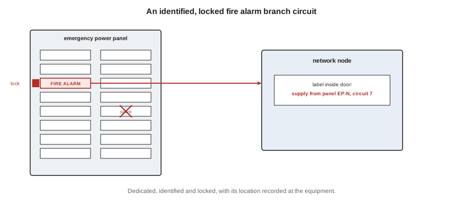
The primary supply for a fire alarm system is a branch circuit from the building's electrical system, and NFPA 72, Chapter 10, and NEC Article 760 set its requirements. The circuit is dedicated to the fire alarm system: no lights or receptacles share it. Its overcurrent device, the breaker, must have a red marking, be accessible only to authorized personnel, be identified as 'FIRE ALARM CIRCUIT', and be locked in the on position so it can't be switched off casually. The location of the branch circuit's disconnecting means is permanently identified at the control unit.
Every piece of equipment that has its own power supply, such as the control unit, each network node, each remote power supply and each amplifier cabinet, gets its own branch circuit, or a supply from the control unit as its listing allows. A remote supply plugged into a convenience receptacle is not acceptable: the receptacle could be switched off, unplugged or shared with a space heater. The branch circuit is sized for the equipment's input current, including the current to charge a fully discharged battery, which the maker's data sheet gives.
The breaker marked 'spare' on the fourth floor is a deficiency on several counts: it isn't identified as a fire alarm circuit, it isn't locked, and the control unit's records won't show where it is. Sasha photographs it and writes it on the list for the electrician to relabel, lock and record.
Connection to emergency power
In many buildings, the fire alarm system's primary power comes from the normal building supply, and its batteries are the secondary supply. In hospitals and some high-rise buildings, there is an emergency generator, and NFPA 99 and NEC Article 517 require the fire alarm to be connected to the life safety branch of the essential electrical system, so that after a power failure the system runs on the generator and the batteries only bridge the gap. NFPA 72 allows a generator to serve as part of the secondary supply, with batteries sized to carry the system until the generator is running and for the time the code specifies. The batteries are still required, because the generator takes time to start and could fail.
For Eastview's north wing, the network node and both remote supplies are fed from the life safety panel in the wing's electrical room, which is on the generator. Sasha checks each branch circuit against the electrical drawings, because a fire alarm supply landed on the normal panel by mistake would work perfectly until the day the power failed.
Installing batteries
Fire alarm batteries are almost always sealed lead-acid, of the type and capacity the design specifies and the charger is listed for. They are installed in the control unit's battery compartment or a listed battery cabinet, never on the floor beside the cabinet or loose on a shelf. Within the cabinet, they sit flat on the bottom or on the shelves provided, not stacked on top of each other, with their terminals protected from contact with the cabinet and each other. The interconnecting cables are the ones supplied with the panel or specified by the maker, tightened to the specified torque, with the polarity checked before the battery is connected.
Each battery is marked with the date it was installed, and often with the date of manufacture, so that later technicians know its age without guessing. Batteries are replaced as a pair or set, and every battery in a set must be the same type, capacity and age, as FAT-130 explained. Old and new batteries are never mixed.
NFPA 72 requires the secondary power calculation to be part of the system's documentation, and many authorities expect a copy in or near the cabinet. The calculation shows the standby and alarm loads, the durations NFPA 72 requires, the safety margin and the battery chosen. When the system is altered, the calculation is redone, because an added appliance or module changes the load.
Large batteries are heavy, and a 55 Ah battery can weigh close to 45 lb. A battery cabinet that will hold large batteries is mounted at or near the floor, or on a stand, so that technicians don't have to lift heavy batteries overhead. The cabinet is located where the batteries stay within their temperature range, because heat shortens battery life and cold reduces capacity. Sealed lead-acid batteries vent small amounts of gas when overcharged, so they are not installed in sealed enclosures beyond what the cabinet's listing allows.
# Battery installation check from the site survey (illustrative data)
from datetime import date
today = date(2026, 11, 20)
sets = [
    {"cab": "Node N-1", "batts": [("12V 26Ah", date(2026, 11, 2)), ("12V 26Ah", date(2026, 11, 2))], "stacked": False},
    {"cab": "RPS-3", "batts": [("12V 12Ah", None), ("12V 12Ah", None)], "stacked": False},
    {"cab": "RPS-4", "batts": [("12V 12Ah", date(2026, 11, 3)), ("12V 18Ah", date(2021, 5, 1))], "stacked": True},
]
for s in sets:
    issues = []
    types = {b[0] for b in s["batts"]}
    dates = {b[1] for b in s["batts"]}
    if None in dates: issues.append("installation date not marked")
    if len(types) > 1: issues.append("mixed capacities")
    if len(dates - {None}) > 1: issues.append("mixed ages")
    if s["stacked"]: issues.append("batteries stacked")
print(f"{s['cab']:9s}", "OK" if not issues else "; ".join(issues))Node N-1 OK RPS-3 installation date not marked RPS-4 mixed capacities; mixed ages; batteries stacked
Remote power supplies
Remote power supplies, sometimes called notification power extenders or booster supplies, provide power for notification appliances, door holders or other loads far from the control unit. They are listed for use with the control unit, mounted in accessible, protected locations within their listing, supplied from their own dedicated branch circuit, and fitted with their own batteries sized by the same calculation as the control unit's. They report their troubles, such as loss of AC power, low battery or a ground fault, back to the control unit, usually through a monitor module or a trouble contact wired to an addressable input.
Remote supplies are triggered by the control unit, typically by a notification circuit or a control module, so that their outputs activate when the system goes into alarm. The connection between the control unit and the remote supply is supervised, and the remote supply passes the synchronization signal through to its outputs so that all the strobes stay in step. Where the remote supply's trigger input and its outputs are on different floors or in different fire compartments, the conductors may need fire protection under the survivability rules FAT-130 covered.
A remote supply also needs smoke detection near it where the standard requires, as Lesson 3 described for transponders and remote equipment. On the north wing, each remote supply is in an electrical room with a ceiling smoke detector already covering it, which the design notes.
Supervision of the power supplies
The control unit supervises its own primary power, its batteries and its charger, and reports a trouble when any of them fails. Loss of primary power is reported as a trouble, usually after a short delay so that momentary dips don't cause nuisance troubles; the delay is limited by the standard, and when the building is on generator power the delay prevents a trouble during the transfer. A disconnected or low battery is reported as a trouble. A failed charger is reported as a trouble.
NFPA 72 requires the system to indicate a trouble on loss of primary power, and requires the trouble to be transmitted to the supervising station where the system is monitored. The transmission of an AC power trouble may be delayed, within the limit NFPA 72 sets, so that a widespread power outage doesn't flood the supervising station with signals.
Auxiliary outputs that power other equipment, such as door holders, deserve thought. Magnetic door holders draw power continuously to hold doors open, and they are designed to release the doors when power is removed, whether because of an alarm or a power failure. They are often powered from a separate supply that is not backed up by the fire alarm batteries, so that a power failure releases the doors and the fire alarm batteries aren't drained holding doors open. The design states which loads are on battery and which are not, and the battery calculation follows the design.
Before the power is turned on
Before Gerry energizes the north wing's equipment, Sasha's checklist must be complete: each branch circuit identified, locked and recorded; each piece of equipment fed from the correct panel; batteries installed, connected with the right polarity, dated and matched; battery calculations in the cabinets; field wiring tested and recorded; and grounding connected as the maker requires. Then the AC supply is turned on first, the panel powers up, and the batteries are connected last, as most makers direct, after which the charger is checked for its output voltage and the battery voltage is recorded.
The first power-up of an addressable node usually shows a long list of troubles: devices not yet installed, circuits not yet terminated, and modules not yet programmed. Gerry clears them one by one, starting with the power and ground faults, because a ground fault can make other faults look like something they aren't.
Worked problem
The fourth-floor remote supply
Sasha's survey of RPS-4 on the north wing's fourth floor finds: a breaker marked 'spare' and not locked; one 12 Ah battery dated last week and one 18 Ah battery dated five years ago, stacked on top of each other; and no battery calculation in the cabinet. What must be done before it is energized?
Show solution
- The branch circuit: the electrician relabels the breaker as the fire alarm circuit, fits the lock-on device and red marking, confirms it is on the life safety panel, and the circuit's location is recorded at the control unit.
- The batteries: remove both and install a matched pair of the capacity the calculation requires, new and of the same type and date, placed flat in the cabinet with terminals protected, and marked with the installation date.
- The calculation: obtain RPS-4's battery calculation from Ravi, check that the battery chosen matches it, and place a copy in the cabinet.
- Check the supervision: confirm the supply's trouble contact reports to the control unit and that the sync signal passes through.
- Record the battery voltage and charger output after power-up.
Answer: The supply is installed as the standard and the design require, with records that let the next technician trust what they see.
Grounding and ground fault detection
Most fire alarm control units are connected to the building's grounding system through their power supply cord or a separate grounding terminal, as the maker specifies. The ground connection is important for safety and for the panel's ground fault detection, which reports any connection between a field conductor and ground as a trouble. A panel installed without its ground connection may not detect ground faults correctly, and some panels report a trouble until it is made.
Remote power supplies and other cabinets are grounded the same way. Where field circuits run between buildings or between power supplies with separate grounds, the maker's instructions may call for isolation or surge protection to prevent ground currents. Sasha checks each cabinet's ground connection against the maker's manual before power-up, because a missing ground is easy to fix now and hard to diagnose later, when it shows up as an intermittent ground fault that comes and goes with the weather.
Common mistakes
MistakeFeeding a fire alarm power supply from a shared or unidentified circuit.
InsteadUse a dedicated, identified, locked branch circuit, recorded at the control unit.
MistakeLanding an emergency-backed supply on the normal panel.
InsteadCheck each branch circuit against the electrical drawings.
MistakeStacking batteries or leaving them loose.
InsteadPlace batteries flat in the listed cabinet with terminals protected.
MistakeMixing old and new or different-capacity batteries.
InsteadInstall matched sets of the same type, capacity and age.
MistakeLeaving batteries undated.
InsteadMark each battery with its installation date.
Summary and key terms
- The primary supply is a dedicated branch circuit, identified, locked and recorded at the control unit.
- Each power supply has its own branch circuit; receptacles aren't used.
- In hospitals, fire alarm supplies are on the emergency power branch for life safety.
- Batteries are matched, dated, installed flat in listed cabinets, with the calculation documented.
- Remote supplies are listed, supervised, synchronized and powered like the control unit.
- The system supervises its primary power, batteries and charger.
- Branch circuit
- The circuit from the last overcurrent device to the load.
- Lock-on device
- A device that prevents a breaker from being switched off casually.
- Essential electrical system
- The part of a facility’s electrical system served by the generator.
- Remote power supply
- A supply that powers appliances or loads away from the control unit.
- Charger
- The circuit that keeps the batteries charged.
- Door holder
- A magnet that holds a door open and releases it when power is removed.
Practice problems
Work each problem on paper first, then reveal the answer to check.
Why must a fire alarm supply not use a convenience receptacle?
Show answer
It could be switched off, unplugged or overloaded.
What must be recorded at the control unit about its supply?
Show answer
The location of its branch circuit.
Why are batteries still needed when there is a generator?
Show answer
The generator takes time to start and could fail.
What is marked on each battery when it is installed?
Show answer
Its installation date.
Why are door holders often not on battery power?
Show answer
So a power failure releases the doors and doesn't drain the batteries.
Lesson quiz · 5 questions
Score 60% or more to complete this lesson.
Create a free account to save your progress, take quizzes and earn a certificate.