
ELEC-420 · Lesson 8 of 12 · 25 min
Troubleshooting control systems, PLCs and networks
Modern machines and buildings are controlled by PLCs, relays, sensors, drives, HMIs and networks. When a machine stops, the cause may be a failed sensor, a misadjusted limit switch, a blown output fuse, a wiring fault, a network problem, a program condition or a safety circuit that has done exactly what it was designed to do. Control troubleshooting combines the electrical skills of earlier lessons with an understanding of logic and communications. This lesson covers reading the machine's own diagnostics, tracing ladder logic online, testing inputs and outputs, analog signal problems, safety circuit faults, network diagnostics and the disciplined handling of program changes and forcing.
Start with what the system tells you
Control systems often know what is wrong. HMI alarm screens, PLC fault and status indicators, drive fault codes, safety relay LEDs and network module status lights provide the first clues. Alarm histories show the sequence of events: which alarm came first, which followed as a consequence, and whether the problem has recurred. A first-out alarm, which records the first of several simultaneous trips, is especially valuable on complex machines where one fault triggers a cascade. Operators can describe what the machine was doing when it stopped, and the machine's sequence step or state, often displayed on the HMI, indicates what condition it is waiting for. Reading these sources carefully before opening any enclosure saves time and reduces risk.
Understanding the sequence
Most machines run sequences: a step does not advance until certain conditions are met. A packaging machine might wait in "infeed ready" until a product sensor sees a carton, a guard is closed, the air pressure is adequate and the previous cycle is complete. When the machine stops, the question is which condition is missing. Sequence documentation, function descriptions and the PLC program itself answer this. Many programs include diagnostic screens showing each permissive and interlock with its status, which turns a search through hundreds of rungs into a quick look at a list of red and green indicators.
Tracing ladder logic online
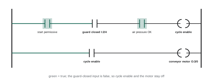
With programming software connected to the PLC online, the ladder logic is displayed with live status: contacts and coils that are true are highlighted. To find why an output is not energized, go to the rung that controls it and look for the condition that is false; then find what controls that condition, and so on back to a physical input or an internal condition. Cross-reference tools list every place an address is used, so you can find all rungs that write to a coil or read an input. Common discoveries include an input that is off because a sensor is misaligned or failed, a timer that has not finished, a latched fault bit that needs a reset, an interlock from another machine, or a value outside a permitted range.
Worked problem
Tracing a missing permissive
A conveyor will not start. Online, the motor output rung shows the "cycle enable" contact false. The cycle enable rung requires start permissive, guard closed (input I:2/4) and air OK, and shows I:2/4 false. What next?
Show solution
- Check the I:2/4 input indicator on the input module: it is off.
- Go to the guard: it appears closed. Check the guard switch: its actuator is misaligned and not engaging.
- Measure voltage at the input terminal while operating the switch by hand: 24 V appears when actuated, confirming wiring is good.
- Realign the actuator and confirm I:2/4 turns on with the guard closed and off when open.
- Test the guard function to confirm the conveyor stops when the guard is opened, then return the machine to the operator.
Answer: A misaligned guard switch actuator kept the input off; realign and test the guard function.
Testing inputs and outputs
The boundary between the PLC and the field is where many faults occur, and it is tested from both sides:
- Inputs: compare the field device state, the voltage at the input terminal and the input module indicator and program status. If the device is actuated and voltage is present at the terminal but the indicator is off, suspect the module or a missing common; if there is no voltage, the problem is in the device or wiring. Remember sinking and sourcing conventions: a PNP (sourcing) sensor supplies positive voltage to a sinking input, and a mismatch prevents the input from turning on.
- Outputs: if the program shows an output on and the module indicator is lit but the load does not operate, check the output fuse, the voltage at the output terminal and at the load, and the load itself. If the indicator is lit but no voltage appears, the output channel may be failed; relay outputs wear, and transistor outputs can be destroyed by overloads or by inductive loads without suppression.
- Wiring: loose terminals, broken conductors in moving cable tracks and damaged connectors on sensors are common, especially on machines with motion and vibration.
Analog signals from Lesson 5 of ELEC-410 apply here too: measure loop current or voltage, check scaling in the program, and confirm the value the program sees matches the field measurement.
| Observation | Likely location of fault | Next check |
|---|---|---|
| Device actuated, no voltage at input terminal | Device or field wiring | Voltage at device, wiring continuity |
| Voltage at terminal, input indicator off | Module, common or sink/source mismatch | Module common, specifications |
| Input indicator on, program bit off | Addressing or program | Configuration, mapping, forced bits |
| Output bit on, indicator off | Program, module or forcing | Module status, configuration |
| Output indicator on, no voltage at terminal | Output fuse or channel | Fuse, channel, supply to module |
| Voltage at load, load not operating | Load or its connection | Coil, motor, solenoid, mechanical |
Safety circuits
Safety circuits, such as emergency stops, guard interlocks, light curtains and safety relays or safety PLCs (ELEC-330), stop machines when a hazard is detected, and they are designed so that faults result in a stop. A machine that will not start because a safety circuit is open is usually working correctly; the task is to find which device is open or faulted, not to get around it. Safety relays indicate the state of each channel with LEDs, and dual-channel circuits detect discrepancies between channels, such as one contact of an emergency stop welded closed while the other opens, latching a fault that requires investigation and reset. Safety devices must never be bypassed, jumpered or defeated during troubleshooting unless done under a documented procedure with alternative protective measures; after any repair, the safety function must be tested to confirm it stops the machine.
Network and communication faults
Machines and plants rely on industrial networks such as EtherNet/IP, PROFINET, Modbus TCP, Modbus RTU, DeviceNet and IO-Link. Communication faults produce symptoms such as I/O modules or drives dropping offline, HMIs showing stale data or communication error banners, and intermittent stops. Troubleshooting steps include:
- Check status indicators on network modules, switches and devices; link lights show physical connectivity, and module status lights show configuration or connection errors.
- Use diagnostic pages in managed switches and PLC software to see which devices are connected, error counters and connection timeouts.
- Check physical layers: damaged or poorly terminated cables and connectors, cables routed next to drive output cables, missing terminating resistors on RS-485 networks, and incorrect shield grounding.
- Check configuration: duplicate IP addresses or node numbers, wrong subnet settings, firmware mismatches after a device replacement, and devices replaced without loading the correct configuration.
- Check network load and design: too many devices, excessive update rates, or uncontrolled traffic from office networks can cause timeouts; segmentation and managed switches help.
Replacement of a failed device often requires setting the correct address and parameters; keeping a record of every device's configuration, and using automatic device replacement features where available, avoids long delays.
Forcing, program changes and documentation
PLC software allows inputs and outputs to be forced on or off regardless of the field state, and programs to be edited online. These tools are powerful and dangerous. A forced output can start equipment unexpectedly; a forced input can defeat an interlock; an online edit can stop a running process if made incorrectly. Good practice requires following site procedures, which often include permits and a second person, informing operators, making sure no one is in the machine's hazard zone, documenting every force, removing all forces before leaving, and never forcing safety signals. Program changes should be made by authorized people, backed up before and after, commented clearly and recorded through management of change, and the old version kept so it can be restored. Many unexplained machine behaviors trace back to a forgotten force or an undocumented program change.
Building diagnostics into systems
Troubleshooting is much faster on systems designed to be diagnosed. Good designs include descriptive alarm messages that say what is wrong and where ("Guard door 3 open" rather than "Fault 27"), first-out logic, permissive and interlock status screens, device-level diagnostics from smart sensors and drives, network diagnostic pages, labeled wiring and terminal numbers that match drawings, and up-to-date program comments. Electricians and technicians who troubleshoot systems should feed back to designers what would have helped, so that the next system is easier to maintain.
Sensors and their failure modes
Field sensors fail in characteristic ways. Inductive proximity sensors may be knocked out of position, coated with metal chips or damaged by impact; photoelectric sensors suffer from dirty lenses, misalignment, reflector damage and changes in ambient light; mechanical limit switches wear and their actuators bend; pressure switches drift or stick; and encoders lose counts from electrical noise, loose couplings or damaged cables. Most sensors have indicator LEDs that show their output state and sometimes signal strength, which allows quick checks: an LED that flickers as a product passes indicates marginal detection. Sensor cables on moving parts break internally from repeated flexing, often producing intermittent faults that appear only when the machine is in a particular position. Flexing the cable gently while watching the input status helps locate such breaks.
Power supplies for control systems
Control power supplies, usually 24 V DC, feed PLCs, sensors, solenoids and safety devices. A failing supply can cause strange intermittent faults across many devices at once: PLC resets, sensors dropping out, network devices rebooting. Measuring the supply voltage under load, checking for ripple with a meter's AC function on the DC output, and watching for voltage dips when solenoids or other loads switch on reveal weak supplies. Overloaded supplies, failing capacitors in older supplies, and loose terminal connections are common causes. Separating supplies for different functions, for example sensors and outputs, and adding redundancy for critical systems improve reliability.
Electrical noise in control circuits
Electrical noise causes intermittent malfunctions such as false inputs, encoder errors and communication dropouts. Common sources include VFD output cables, contactor coils without suppression, welding equipment and radio transmitters. Remedies include routing control and signal cables away from power cables, using shielded cables with correct shield termination, fitting suppressors (diodes on DC coils, RC snubbers or varistors on AC coils), proper grounding and bonding of enclosures and equipment, and using ferrite cores on susceptible cables.
Finally, keep spare parts and backups organized. A current copy of every PLC and HMI program, drive parameter set and network configuration, stored securely off the machine with version information, allows a failed device to be replaced and restored quickly. Without backups, a single hardware failure can stop production for days while programs are reconstructed.
Common mistakes
MistakeOpening enclosures before reading alarms and history.
InsteadStart with HMI alarms, fault codes and status indicators.
MistakeJumpering safety circuits to get a machine running.
InsteadFind the open safety device; never defeat safety functions.
MistakeLeaving forces in the PLC.
InsteadDocument and remove all forces before leaving.
MistakeReplacing a network device without its configuration.
InsteadKeep and load device addresses and parameters.
MistakeEditing programs without backups or records.
InsteadBack up, comment and record every change.
Summary and key terms
- HMI alarms, first-out indications and fault codes are the first clues.
- Machines wait for missing conditions in their sequence; find which one.
- Online ladder logic shows false conditions; trace back to field inputs.
- Test the I/O boundary from both the field and the program side.
- Safety circuits stopping a machine are usually working correctly.
- Network faults involve physical, configuration and load problems.
- Forcing and online edits require strict procedures and documentation.
- First-out alarm
- Indication of the first of several trips.
- Permissive
- Condition required before an action can start.
- Interlock
- Condition that prevents or stops an action.
- Online monitoring
- Viewing live program status in the PLC.
- Cross-reference
- List of all uses of a program address.
- Sinking input
- Input that completes the circuit to common.
- Sourcing sensor
- Sensor that supplies positive voltage (PNP).
- Forcing
- Overriding an I/O state in the PLC.
- Dual-channel safety circuit
- Redundant safety inputs monitored for discrepancy.
- Management of change
- Formal control of modifications.
Practice problems
Work each problem on paper first, then reveal the answer to check.
What is the value of a first-out alarm?
Show answer
It identifies the initiating fault in a cascade.
How do you find why a PLC output is off?
Show answer
Trace the false conditions on its rung back to inputs.
Voltage present at an input terminal but indicator off. Suspect?
Show answer
Module, common or sink/source mismatch.
Output indicator on but no voltage at the terminal. Suspect?
Show answer
Output fuse or failed channel.
Why do transistor outputs fail with inductive loads?
Show answer
Unsuppressed voltage spikes.
What does a discrepancy fault in a safety relay indicate?
Show answer
The two channels disagree, such as a welded contact.
Name two network configuration faults.
Show answer
Duplicate addresses, wrong subnet, firmware mismatch.
What physical problems cause RS-485 faults?
Show answer
Missing terminators, poor shields, damaged cables.
What must happen before leaving after forcing I/O?
Show answer
All forces documented and removed.
Give an example of a good alarm message.
Show answer
Guard door 3 open.
Lesson quiz · 5 questions
Score 60% or more to complete this lesson.
Create a free account to save your progress, take quizzes and earn a certificate.