
ELEC-420 · Lesson 2 of 12 · 25 min
Test instruments and their safe use
Instruments are the troubleshooter's senses. A good meter, used correctly, reveals voltages, currents, resistances and temperatures that are otherwise invisible; a poor meter, or a good one used wrongly, gives misleading readings or, in the worst case, fails explosively in the user's hands. This lesson covers digital multimeters and their functions, measurement category ratings and why they matter for safety, true RMS measurement, clamp meters, voltage testers and proving units, insulation testers, thermal imaging cameras and other specialized instruments, and the habits that keep measurements accurate and safe.
The digital multimeter
The digital multimeter (DMM) measures AC and DC voltage, AC and DC current, resistance, continuity, and often capacitance, frequency, diode forward voltage and temperature. Key specifications include accuracy (stated as a percentage of reading plus a number of digits, for example ±(0.5 % + 2)), resolution, input impedance, and whether it measures true RMS. Most DMMs have a high input impedance on voltage ranges, typically 10 MΩ, which barely loads the circuit being measured. This is usually an advantage, but it can produce misleading "ghost voltages": capacitive coupling from adjacent energized conductors can make an open, unused conductor read tens of volts. Many meters therefore offer a low-impedance (LoZ) mode, which presents a few kilohms to the circuit and drains coupled voltage, revealing whether a voltage is real. LoZ mode should not be used on sensitive electronic circuits, which it can load or damage.
Worked problem
Reading meter accuracy
A meter specified at ±(0.5 % + 3 digits) on its 600.0 V range reads 230.4 V. What range could the true voltage lie in?
Show solution
- 0.5 % of reading: 0.005 × 230.4 = 1.15 V.
- Three digits on a range with 0.1 V resolution: 3 × 0.1 = 0.3 V.
- Total uncertainty: 1.15 + 0.3 = 1.45 V.
- True value: 230.4 ± 1.45 V, between about 228.9 and 231.9 V.
- This matters when checking against tight limits, such as a drive's undervoltage threshold.
Answer: Between about 228.9 V and 231.9 V.
Measurement categories
Electrical systems experience transient overvoltages from lightning, switching and faults, and the closer you are to the service, the more energy those transients carry. IEC 61010-1 defines measurement categories that rate instruments for the transient environment where they are used:
- CAT IV: the origin of the installation, such as the service entrance, utility meter, overhead and underground service conductors.
- CAT III: distribution within the building: panelboards, switchgear, feeders, busways, permanently installed motors and industrial equipment.
- CAT II: receptacle-connected loads, appliances and portable tools.
- CAT I or "no rated category": protected electronic circuits not directly connected to mains.
A meter rated CAT III 1000 V and CAT IV 600 V withstands much larger transients than a CAT II meter of the same voltage. Using a meter in a higher category than it is rated for risks an arc inside the meter, potentially an arc flash in the user's hands. Test leads, probes and accessories have their own ratings, and the system is only as safe as its lowest-rated part. Look also for independent certification marks from a recognized testing laboratory, because category markings on cheap meters are sometimes unsupported.
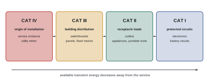
| Category | Location | Examples |
|---|---|---|
| CAT IV | Origin of installation | Service entrance, utility meter, service conductors |
| CAT III | Building distribution | Switchboards, panels, feeders, fixed motors, MCCs |
| CAT II | Receptacle-connected loads | Appliances, portable tools, outlets |
| CAT I / none | Protected secondary circuits | Electronics, battery circuits |
True RMS measurement
Many loads, such as variable frequency drives, LED drivers, computers and switch-mode power supplies, draw non-sinusoidal currents rich in harmonics. Average-responding meters measure the average of the rectified waveform and scale it by the form factor of a pure sine wave (1.11); they read correctly only for sinusoids. On distorted waveforms they can read 30 % or more low for the peaky currents drawn by electronic loads. True RMS meters calculate the actual root-mean-square value, which represents the heating effect of the current, and should be used for all troubleshooting in modern installations. Crest factor, the ratio of peak to RMS value (1.414 for a sine wave), indicates how peaky a waveform is; meters specify the maximum crest factor they can handle accurately.
Clamp meters
Clamp meters measure current without breaking the circuit by sensing the magnetic field around a conductor. Current transformer jaws measure AC; Hall-effect jaws measure both AC and DC, needed for PV, battery and DC drive circuits. Flexible Rogowski coils wrap around large conductors or bundles in tight spaces. Correct use requires clamping around a single conductor: clamping around a cable containing both supply and return conductors reads near zero because their fields cancel, which is the principle used deliberately for leakage current measurements, where all circuit conductors are clamped together and any reading represents current flowing elsewhere, such as through the grounding system. Leakage clamp meters resolve microamperes to milliamperes for this purpose. Clamp meters often include inrush measurement, capturing the starting current of motors, and many include voltage and resistance functions as well.
Voltage testers and proving units
Testing for the absence of voltage before work is the most important measurement an electrician makes, and it deserves a purpose-built instrument. Two-pole voltage testers designed for this task are simple, robust and hard to misuse; they test each phase to phase and phase to ground. Non-contact voltage detectors, which sense the electric field near a conductor, are useful for quick checks but are not reliable proof of absence of voltage, because shielding, distance, DC circuits and low battery can all produce false negatives. Testing for absence of voltage requires the live–dead–live sequence: verify the tester on a known live source, test the circuit, and verify the tester again. A proving unit, a small battery-powered source that generates a test voltage, provides a known live source when none is nearby. Some installations now have permanently mounted absence-of-voltage testers that perform this check automatically at the push of a button.
Insulation resistance testers
Insulation resistance testers, often called megohmmeters or by the trade name Megger, apply a high DC test voltage, typically 250, 500, 1,000, 2,500 or 5,000 V, to measure the resistance of insulation in megohms or gigohms. They are essential for testing cables, motors, transformers and switchgear before energizing and during maintenance (Lesson 3). Because they generate high voltages and can charge cable capacitance to dangerous levels, the circuit under test must be isolated, and conductors must be discharged after testing; most testers discharge automatically and show when the voltage has decayed.
Thermal imaging and other instruments
Thermal imaging cameras show temperature differences across equipment, revealing loose or corroded connections, overloaded conductors, unbalanced phases, failing bearings and blocked cooling. They are the most productive single instrument for finding developing faults in distribution equipment, provided the equipment is under significant load (ideally at least 40 % of rated load) and the operator understands emissivity, reflections and the limits of scanning through enclosures. Infrared windows installed in switchgear allow scanning without opening covers. Other instruments used in troubleshooting include ground resistance testers (Lesson 4), loop impedance and RCD testers, phase rotation meters, power quality analyzers (Lesson 7), oscilloscopes for control and drive circuits, ultrasonic detectors for partial discharge and air leaks, and circuit tracers that locate breakers and buried cables.
Using instruments safely and accurately
Good practice with instruments includes:
- Choose an instrument rated for the voltage and category of the circuit, with leads and accessories of matching rating.
- Inspect leads and probes before use for cracked insulation and exposed metal; use probes with short exposed tips or shrouds.
- Select the function and range before connecting; never measure voltage with the leads in the current jacks, a common cause of meter explosions on energized circuits.
- Use one hand where practical and keep fingers behind probe guards.
- Prove the meter live–dead–live when testing for absence of voltage.
- Keep instruments calibrated, check batteries, and record serial numbers on test reports so results are traceable.
Current measurements with a DMM require breaking the circuit and inserting the meter in series, and the current jacks are protected by fuses that must be the correct high-energy type; a meter fitted with an ordinary fuse can explode if connected across a voltage source while on a current range. Clamp meters avoid this risk and are preferred for current measurement on power circuits.
Caring for instruments
Instruments must be maintained to stay safe and accurate. Test leads deserve regular inspection, because a nick in the insulation near the probe tip is easy to miss and can expose the user to a conductor at full voltage. Replace leads that are cracked, stiff or damaged, and use leads with the same or higher category rating as the meter. Batteries should be replaced when low-battery warnings appear, since some meters give inaccurate readings or fail to detect voltage with weak batteries. Fuses must be replaced only with the exact high-energy types specified by the manufacturer. Instruments dropped or exposed to overvoltage should be checked or calibrated before further use. Calibration at the interval recommended by the manufacturer or required by company procedures, typically annually, with a certificate traceable to national standards, is essential when readings are used for commissioning or compliance records.
Choosing instruments for the job
An electrician's toolkit typically includes a CAT III/IV true RMS multimeter with LoZ mode, a clamp meter with inrush capture (and DC capability if working on PV or batteries), a two-pole voltage tester and proving unit, an insulation tester with at least 1,000 V output and PI timing, a non-contact detector for quick checks, a phase rotation meter and a receptacle tester. Specialized work adds a thermal imager, a power quality analyzer, a loop impedance and RCD tester, a ground resistance tester, a micro-ohmmeter and a process calibrator. Buying quality instruments from reputable manufacturers is a safety decision, not just a matter of convenience: in independent tests, low-cost meters with category markings have failed catastrophically at transient levels they claimed to withstand.
Recording measurements
Measurements are only useful if recorded accurately. Note the instrument used, the range and function, the exact test points, the load conditions, the ambient temperature where relevant, and the time. For commissioning and maintenance tests, use standard forms or software that capture these details consistently, so that results can be compared over time and by different technicians. Many modern instruments store readings and transfer them wirelessly to phones or tablets, reducing transcription errors and creating time-stamped records.
Understanding resolution and loading
Two further measurement concepts help avoid errors. Resolution is the smallest change a meter can display, which is not the same as accuracy: a meter that displays 0.001 V may still be in error by much more than that. And every measurement disturbs the circuit slightly. A voltmeter draws a small current, an ammeter inserted in series adds a small resistance, and an ohmmeter injects current that can turn on semiconductors or charge capacitors. In most power circuits these effects are negligible, but in sensitive control and electronic circuits they can change what you are measuring, so choose instruments and functions appropriate to the circuit.
Finally, match the instrument to the question. A thermal camera shows where heat is, not why; a clamp meter shows current, not voltage quality; a multimeter shows an average value, not the brief sag that reset a controller. When an instrument cannot answer the question you are asking, choose a different one rather than over-interpreting its readings.
Common mistakes
MistakeUsing a CAT II meter in a switchboard.
InsteadUse instruments rated CAT III or CAT IV for the location.
MistakeRelying on a non-contact detector to prove a circuit dead.
InsteadUse a two-pole tester with live–dead–live.
MistakeMeasuring distorted currents with an average-responding meter.
InsteadUse a true RMS meter.
MistakeClamping around a whole cable to measure load current.
InsteadClamp a single conductor.
MistakeLeaving leads in the current jacks.
InsteadCheck leads and function before every voltage test.
Summary and key terms
- DMMs measure voltage, current, resistance and more; know their accuracy.
- LoZ mode distinguishes real voltages from ghost voltages.
- Measurement categories rate instruments for transient energy by location.
- True RMS meters read distorted waveforms correctly.
- Clamp meters measure current without breaking circuits; leakage clamps detect ground currents.
- Prove absence of voltage with a two-pole tester and live–dead–live.
- Insulation testers and thermal cameras reveal developing faults.
- DMM
- Digital multimeter.
- Input impedance
- Resistance a meter presents to the circuit.
- Ghost voltage
- Coupled voltage on an open conductor.
- LoZ mode
- Low-impedance voltage measurement mode.
- Measurement category
- IEC rating for transient withstand by location.
- True RMS
- Measurement of actual heating value of a waveform.
- Crest factor
- Ratio of peak to RMS value.
- Clamp meter
- Meter measuring current through jaws around a conductor.
- Proving unit
- Portable known voltage source for testing testers.
- Megohmmeter
- High-voltage insulation resistance tester.
Practice problems
Work each problem on paper first, then reveal the answer to check.
Why do ghost voltages occur?
Show answer
Capacitive coupling into a high-impedance meter.
What does LoZ mode do?
Show answer
Loads the circuit to drain coupled voltage.
Which category covers a panelboard?
Show answer
CAT III.
Which category covers the service entrance?
Show answer
CAT IV.
Why use true RMS meters?
Show answer
Non-sinusoidal waveforms read wrongly on average-responding meters.
Crest factor of a sine wave?
Show answer
1.414.
What do you read clamping all conductors of a circuit?
Show answer
Leakage current.
Why not use non-contact detectors to prove dead?
Show answer
False negatives from shielding, DC or distance.
Meter ±(1 % + 2), 0.1 V resolution, reads 120.0 V. Range?
Show answer
±1.4 V: 118.6 to 121.4 V.
Why load circuits for thermal imaging?
Show answer
Faults heat only under significant load.
Lesson quiz · 5 questions
Score 60% or more to complete this lesson.
Create a free account to save your progress, take quizzes and earn a certificate.