
ELEC-420 · Lesson 6 of 12 · 27 min
Troubleshooting motors, starters and drives
Motors drive most of the machinery in industry and commercial buildings, and motor-related problems account for a large share of maintenance calls. A motor that will not start, trips on overload, runs hot, vibrates or makes noise can have causes in the supply, the controls, the motor itself or the driven load. ELEC-310 covered how motors and controls work; this lesson applies the troubleshooting method to them, covering supply checks, starter and control circuit faults, winding and insulation tests, current and voltage imbalance, bearing and mechanical problems, and fault diagnosis in variable frequency drives.
Start with the symptom and the system
Motor problems are classified first by symptom, because each symptom points to a different set of causes:
- Motor will not start and makes no sound: no power, an open control circuit, a tripped overload, a failed starter or contactor, or an open winding.
- Motor hums but will not start: single phasing (a missing phase), very low voltage, a locked rotor from a seized bearing or jammed load, or for single-phase motors a failed start capacitor or centrifugal switch.
- Motor starts but trips the overload: overload from the driven equipment, low or unbalanced voltage, wrong overload setting, high ambient temperature, or frequent starting.
- Motor trips the breaker or blows fuses instantly: a winding short or ground fault, a cable fault, or a wrongly sized protective device for the starting current.
- Motor runs hot, noisy or vibrating: overload, voltage problems, misalignment, bearing failure, unbalance, blocked ventilation or a loose mounting.
Before testing, check the obvious: is the disconnect closed, the breaker on, the overload reset, the emergency stop released, the control in the correct mode (hand, off, auto), and the PLC or interlock calling for the motor to run? Many service calls end at this step.
| Symptom | Likely causes | First checks |
|---|---|---|
| No start, silent | No supply, open control circuit, tripped overload | Voltage at starter, control circuit, overload |
| Hums, will not start | Single phasing, low voltage, locked rotor | Voltage on all three phases, rotor free to turn |
| Trips overload | Mechanical overload, voltage imbalance, setting | Running current, voltage balance, overload setting |
| Instant breaker trip | Winding or cable short, ground fault | Insulation resistance, winding resistance |
| Runs hot | Overload, low voltage, poor cooling | Current, voltage, fan and vents |
| Noise, vibration | Bearings, alignment, unbalance, looseness | Vibration, bearing temperature, coupling |
Supply and starter checks
With the motor running or attempting to start, measure voltage at the motor terminals or the load side of the starter on all three phases, phase to phase. Voltage should be within about ±10 % of the nameplate, and balanced. A missing phase while the motor is running may not be obvious at the starter line side, because a running three-phase motor regenerates voltage on the open phase, so measure current as well: a phase with zero current indicates single phasing. Then work back through the starter: voltage across each contactor pole under load should be near zero; overload heater or electronic overload settings should match the nameplate full-load current and service factor; and control voltage should be present at the coil when the motor is called to run. If the coil is energized but the contactor does not pull in, the coil or mechanism has failed; if the coil is not energized, troubleshoot the control circuit with the half-splitting method from Lesson 1.
Voltage and current imbalance
Three-phase motors are sensitive to voltage imbalance. A small voltage imbalance produces a much larger current imbalance, because the unbalanced component creates a negative-sequence field that opposes rotation and induces large rotor currents. As a rule of thumb, the percentage temperature rise in the hottest winding is about twice the square of the percentage voltage imbalance: 3 % imbalance causes about 18 % additional heating. NEMA MG 1 defines voltage imbalance as the maximum deviation from the average divided by the average, recommends derating motors when imbalance exceeds 1 %, and advises against operation above 5 %.
Worked problem
Calculating voltage imbalance
A 460 V motor has line voltages of 462 V, 450 V and 441 V. Calculate the voltage imbalance and estimate the extra winding heating.
Show solution
- Average voltage: (462 + 450 + 441) / 3 = 451 V.
- Deviations: 11, 1 and 10 V; the maximum is 11 V.
- Imbalance: 11 / 451 × 100 ≈ 2.4 %.
- Extra heating ≈ 2 × 2.4² ≈ 11.5 % in the hottest winding.
- Above 1 %, the motor should be derated; investigate unbalanced single-phase loads, a high-resistance connection or a utility problem.
Answer: About 2.4 % imbalance, causing roughly 12 % extra heating; find and correct the cause.
Current imbalance is diagnosed by measuring all three phase currents. To tell whether the imbalance comes from the supply or the motor, rotate the motor leads: move all three motor leads one position at the starter (A to B, B to C, C to A), keeping the same rotation direction, and measure again. If the high current stays with the same supply phase, the supply is unbalanced; if it follows the same motor lead, the problem is in the motor or its cable, such as a winding fault or a bad connection.
Winding and insulation tests
With the motor locked out and disconnected from its supply, several tests assess the windings:
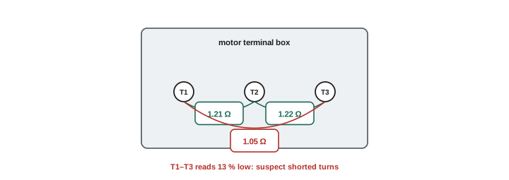
- Winding resistance: measure the resistance of each phase winding (or between each pair of leads) with a low-resistance ohmmeter. Readings should be within a few percent of each other; an imbalance suggests shorted turns, a high-resistance connection or an open in a parallel winding path.
- Insulation resistance and polarization index to ground (Lesson 3), detecting moisture, contamination and insulation breakdown.
- Surge comparison testing, which applies fast high-voltage pulses to each phase and compares the resulting waveforms, detecting turn-to-turn and phase-to-phase insulation weaknesses invisible to resistance tests.
- Motor circuit analysis instruments that measure inductance and impedance imbalance, detecting rotor bar problems and turn faults with low-voltage tests.
Testing the motor and its cable separately, by disconnecting the cable at the motor terminal box, shows whether a fault is in the motor or the feeder.
Mechanical and bearing problems
Many apparent electrical problems are mechanical. A pump with a clogged impeller, a conveyor with a seized roller, a fan with a damaged blade or a gearbox with failing bearings all increase motor load or vibration. Checks include rotating the shaft by hand with the motor locked out to feel for binding or roughness, inspecting couplings, belts and alignment, and measuring vibration and bearing temperatures. Bearing failure is the most common cause of motor failure overall. Causes include insufficient or excessive lubrication, contamination, misalignment, overloaded belts and, in motors fed by VFDs, electrical discharge machining, where shaft voltages induced by the drive discharge through the bearings and etch the races, producing a characteristic fluted pattern and noise. Shaft grounding rings, insulated bearings and proper drive cable installation prevent this.
Troubleshooting variable frequency drives
VFDs report many faults through codes and logs, which are the first source of information: overcurrent, overvoltage, undervoltage, ground fault, overtemperature, motor overload, phase loss and communication faults. Interpreting them correctly narrows the search:
- Overcurrent on acceleration: acceleration time too short, mechanical binding, motor or cable fault, or wrong motor data in the drive.
- Overvoltage on deceleration: the load drives the motor as a generator, raising the DC bus; lengthen the deceleration time or add dynamic braking.
- Undervoltage: supply sags or loss of a phase on the drive input.
- Ground fault: motor or cable insulation failure, often moisture in the motor or terminal box, or long cables with high capacitive leakage.
- Overtemperature: blocked filters, failed cooling fans, high ambient temperature or excessive load.
Safe work on drives requires attention to stored energy: the DC bus capacitors hold dangerous voltage after the drive is disconnected, so wait the time specified on the drive and measure the DC bus voltage before touching internal components. Drives can be tested by disconnecting the motor and running the drive unloaded to see whether output voltages are balanced, and by testing the motor separately. Measurements on drive outputs require true RMS meters with low-pass filter modes designed for VFD outputs, because ordinary meters give misleading readings on pulse-width-modulated waveforms.
Worked problem
Diagnosing a drive fault
A fan VFD trips on overvoltage every time the fan is stopped. The fan has a large, heavy impeller and the deceleration time is 5 s. What is happening and what are the options?
Show solution
- When the drive lowers frequency, the heavy impeller keeps turning faster than the field, so the motor acts as a generator.
- Regenerated energy flows back into the DC bus, raising its voltage until the drive trips.
- Option 1: lengthen the deceleration time (for example to 30 s) so energy is dissipated by friction and air resistance.
- Option 2: set the stop mode to coast, if stopping time is not critical.
- Option 3: add a dynamic braking resistor or regenerative unit if fast stopping is required.
Answer: Regeneration during deceleration raises the DC bus; lengthen deceleration, coast to stop, or add braking.
Single-phase motors
Single-phase motors, common in pumps, compressors, fans and appliances, have specific failure modes. Capacitor-start and capacitor-run motors depend on capacitors to create the phase shift needed for starting torque; a failed start capacitor leaves the motor humming without starting, while a weak run capacitor reduces running torque and increases current. Capacitors can be tested with a capacitance meter after discharging them safely, and should be within the tolerance marked on them, typically ±6 % for run capacitors. Centrifugal switches that disconnect the start winding can stick closed, overheating the start winding, or fail open, preventing starting. Hermetic compressors in refrigeration and air conditioning equipment have start relays and overload protectors that are frequent failure points, and diagnosing them requires knowing the start, run and common terminals, identified by resistance measurements between the three terminals: the largest reading is between start and run, and the other two add up to it.
Recording baseline data
The best time to gather information for future troubleshooting is when equipment is new and working well. Recording running currents on each phase, voltages, insulation resistance, winding resistance, vibration levels and temperatures at commissioning provides a baseline. When a problem appears later, comparing current readings with the baseline shows immediately what has changed, turning guesswork into straightforward comparison. Many maintenance programs record these values periodically for critical motors to build trend data.
Starters and contactors
Contactors and starters wear with use. Contacts pit and erode from arcing each time they open under load, eventually increasing resistance and causing heating or welding. Coils can fail open or shorted, or burn out when supplied with the wrong voltage, a common error when replacing coils. Mechanical parts can stick from dirt or wear. Inspection of contacts, measurement of voltage drop across each pole under load, and checks of coil voltage and resistance identify these problems. Replace contacts in sets, never singly, to keep poles matched.
Motor protection settings
Many repeat motor trips trace back to protection settings rather than faults. Overload relays must be set according to the motor nameplate full-load current and service factor, adjusted for any ambient temperature difference between motor and controller, and electronic overloads often provide additional settings for phase loss, imbalance, ground fault and jam protection. Settings copied from a previous motor of a different size, or left at defaults, either trip unnecessarily or fail to protect. Checking settings against the nameplate is a quick early step in any motor troubleshooting call.
Common mistakes
MistakeResetting overloads repeatedly without finding the cause.
InsteadMeasure current, voltage balance and load.
MistakeAssuming a running motor has all three phases.
InsteadMeasure current on every phase.
MistakeTesting motor and cable together only.
InsteadSeparate them to locate the fault.
MistakeMeasuring VFD output with an ordinary meter.
InsteadUse a meter with a VFD low-pass mode.
MistakeOpening a drive immediately after shutdown.
InsteadWait and verify the DC bus is discharged.
Summary and key terms
- Classify motor problems by symptom before testing.
- Check supply voltage and current on all phases and each starter pole.
- Small voltage imbalance causes large current imbalance and heating.
- Rotating motor leads shows whether imbalance comes from supply or motor.
- Winding resistance, IR, PI and surge tests assess motor windings.
- Bearings and mechanical loads cause many apparent electrical faults.
- VFD fault codes guide diagnosis; respect stored DC bus energy.
- Single phasing
- Loss of one phase to a three-phase motor.
- Locked rotor
- Rotor unable to turn, drawing starting current.
- Voltage imbalance
- Unequal phase voltages.
- Negative sequence
- Component of imbalance opposing rotation.
- Lead rotation test
- Moving motor leads to locate imbalance source.
- Winding resistance test
- Comparing phase winding resistances.
- Surge comparison test
- High-voltage pulse test for turn faults.
- Electrical discharge machining
- Bearing damage from shaft currents.
- Regeneration
- Motor acting as a generator during deceleration.
- Dynamic braking
- Dissipating regenerated energy in a resistor.
Practice problems
Work each problem on paper first, then reveal the answer to check.
What does a motor that hums but will not start suggest?
Show answer
Single phasing, low voltage or a locked rotor.
Why might voltage appear on an open phase?
Show answer
A running motor regenerates voltage on it.
Voltages 480, 470, 455 V: imbalance?
Show answer
Average 468.3; max deviation 13.3; about 2.8 %.
Extra heating for 2 % imbalance?
Show answer
About 8 %.
High current follows the motor lead after rotation. Where is the fault?
Show answer
In the motor or its cable.
What does a low winding resistance on one pair suggest?
Show answer
Shorted turns.
What test detects turn-to-turn faults?
Show answer
Surge comparison testing.
What causes fluted bearing races in VFD motors?
Show answer
Shaft current discharges.
Cause of overvoltage trips on deceleration?
Show answer
Regenerated energy raising the DC bus.
What must be checked before opening a drive?
Show answer
That the DC bus has discharged.
Lesson quiz · 5 questions
Score 60% or more to complete this lesson.
Create a free account to save your progress, take quizzes and earn a certificate.