
ELEC-420 · Lesson 4 of 12 · 27 min
Testing grounding, bonding and fault protection
Grounding and bonding are invisible until something goes wrong. When insulation fails and a live conductor touches a metal enclosure, a low-impedance fault path must carry enough current to trip the protective device quickly, and bonding must keep exposed metal at a safe potential. A grounding electrode system must also connect the installation to earth to limit voltages from lightning, utility faults and static. Testing proves these systems will perform. This lesson covers measuring grounding electrode resistance with the fall-of-potential and clamp-on methods, testing the effectiveness of fault paths with loop impedance measurements, testing ground-fault circuit interrupters and residual current devices, testing ground-fault protection of equipment, and finding problems such as neutral-to-ground faults and objectionable current.
Functions of grounding and bonding
It helps to separate functions that are often confused:
- System grounding connects one conductor of the supply, usually the neutral, to earth, stabilizing voltage to ground and limiting overvoltages.
- The grounding electrode system (rods, plates, building steel, water pipes, concrete-encased electrodes, rings) connects the installation to earth.
- Equipment bonding connects all exposed metal parts together and to the system grounded conductor at the service, forming a low-impedance fault return path.
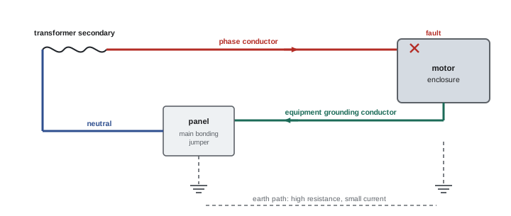
The fault return path, not the earth, is what trips breakers on a ground fault in a solidly grounded system. Earth resistance is far too high to carry enough fault current: a 25 Ω electrode on a 120 V circuit passes at most about 5 A, which would not trip a 20 A breaker. A low-impedance metallic path back to the source, through equipment grounding conductors and the main bonding jumper, is essential. Testing therefore addresses both the electrode system and the fault path.
Measuring grounding electrode resistance
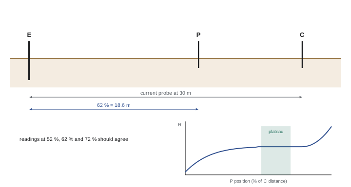
The fall-of-potential method, the classic three-point test, uses a ground resistance tester with three connections: the electrode under test (E), a potential probe (P) and a current probe (C) driven into the earth at a distance. The tester injects current between E and C and measures voltage between E and P; resistance is voltage divided by current. For accurate results, the current probe must be far enough away, commonly at least five to ten times the electrode's length or the diagonal of an electrode grid, and the potential probe is placed at 62 % of the distance from E to C, where the measured resistance approximates the true value for a hemispherical electrode. Taking readings with the potential probe at several positions and finding a flat region in the curve confirms the result.
Worked problem
Planning a fall-of-potential test
A single 3 m ground rod is to be tested. Where should the current and potential probes be placed, and how do you confirm the reading?
Show solution
- Place the current probe at least 10 times the rod length away: 30 m from the rod.
- Place the potential probe at 62 % of that distance: 0.62 × 30 = 18.6 m, in a straight line.
- Take readings with the potential probe at 52 % and 72 % (about 15.6 m and 21.6 m) as well.
- If the three readings agree within about 5 %, the 62 % reading is valid.
- If they differ widely, move the current probe further away and repeat.
Answer: Current probe at 30 m, potential probe at 18.6 m, confirmed by readings at 52 % and 72 %.
The clamp-on (stakeless) method measures the resistance of an electrode in a multi-grounded system, such as utility poles or buildings with several electrodes in parallel, by inducing a voltage in the grounding loop with a clamp and measuring the resulting current. It requires no probes or disconnection, but it works only when parallel return paths exist, and it measures the whole loop resistance, so its results must be interpreted carefully. Soil resistivity testing with four equally spaced probes (the Wenner method) measures soil properties before designing electrode systems.
In the United States, NEC 250.53 requires a single rod, pipe or plate electrode to be supplemented by a second electrode unless its resistance to earth is 25 Ω or less, and engineers often specify much lower values, such as 5 Ω or less, for data centers, substations and telecommunication facilities.
Testing the fault path: loop impedance
The effectiveness of the fault return path is measured by earth fault loop impedance: the total impedance of the path from the source through the phase conductor to the fault and back through the protective conductor. A loop impedance tester draws a brief test current between the phase and protective conductor at the point of measurement and calculates the impedance from the voltage drop. From the impedance, the prospective fault current follows:
where \(U_0\) is the nominal voltage to ground. The fault current must be high enough to operate the protective device within the required time. For a breaker with instantaneous trip at, say, ten times its rating, the loop impedance must be low enough to deliver at least that current. Loop impedance testing is standard in IEC countries and increasingly used in North America to verify that equipment grounding conductors, especially long runs and those using raceways as the grounding path, will clear faults. Neutral–ground and phase–neutral loop measurements also reveal high-resistance connections.
Worked problem
Checking fault clearing with loop impedance
At a 120 V receptacle protected by a 20 A breaker with an instantaneous trip at about 10 times its rating, the measured phase–ground loop impedance is 0.9 Ω. Will a bolted ground fault trip the breaker instantaneously?
Show solution
- Prospective fault current: 120 / 0.9 ≈ 133 A.
- Instantaneous trip requires about 10 × 20 = 200 A.
- 133 A is below 200 A, so the breaker would trip on its slower thermal element, possibly taking seconds.
- Find and correct high-resistance connections, or check whether the run length requires a larger grounding conductor.
- An impedance of 0.6 Ω or less would give at least 200 A.
Answer: No; about 133 A is below the 200 A instantaneous threshold, so fault clearing would be slow.
Testing GFCIs and RCDs
Ground-fault circuit interrupters (GFCIs) in North America and residual current devices (RCDs) elsewhere protect people from shock by tripping when the current in the phase and neutral conductors differs by more than a small amount, indicating current leaking to ground, possibly through a person. North American Class A GFCIs trip at 4 to 6 mA within a time that decreases with current, typically within about 25 ms at high leakage currents; RCDs commonly trip at 30 mA. The built-in test button checks the mechanism by creating an imbalance internally, but does not verify the wiring; a plug-in tester that creates a measured leakage from phase to ground verifies that the device trips through the actual protective conductor. Dedicated RCD testers measure trip current and trip time accurately. Testing should be done at installation and periodically, and devices that fail to trip must be replaced. Note that GFCI testers require an equipment grounding conductor to create the test leakage; on two-wire circuits without a ground, use only the device's own test button.
Ground-fault protection of equipment
Large services and feeders, typically 1,000 A and above on solidly grounded wye systems over 150 V to ground, are often required to have ground-fault protection of equipment (GFPE), which trips the main breaker or switch on ground faults of a few hundred amperes that would otherwise burn without tripping phase overcurrent devices. GFPE must be performance-tested when first installed, by primary current injection through the sensor or by methods the manufacturer specifies, to confirm correct sensor polarity, neutral connections, pickup and time settings, and that the device actually opens. A common installation error is a neutral bonded to ground downstream of the GFPE sensor, which creates parallel return paths that desensitize or falsely trip the protection.
Finding neutral–ground faults and objectionable current
In a properly installed system, the neutral is bonded to ground only at the service (or at a separately derived system). Additional neutral-to-ground connections downstream, from a misplaced bonding jumper in a subpanel, a neutral touching an enclosure, or a miswired device, allow normal neutral current to flow on equipment grounding conductors, conduits and building steel. This objectionable current causes nuisance tripping of GFPE and GFCIs, electrical noise, shock hazards and corrosion. Symptoms include current measured on grounding conductors with a clamp meter during normal operation, and voltage between neutral and ground at the service that is lower than expected at loads. To locate the extra bond, measure current on the equipment grounding conductor of each feeder and branch circuit, isolate subpanels one at a time with the main neutral disconnected (under lockout), and test insulation resistance between the neutral and ground buses in subpanels, which should be very high when the neutral is properly isolated.
| Test | Purpose | Typical acceptance guidance |
|---|---|---|
| Electrode resistance (fall of potential) | Connection to earth | 25 Ω or less for single electrodes in many codes; lower by specification |
| Bonding continuity | Low-resistance bonding paths | Close to calculated conductor resistance |
| Earth fault loop impedance | Fault clearing capability | Low enough to trip protection in required time |
| GFCI / RCD trip test | Shock protection | Trip within rated current and time |
| GFPE performance test | Equipment ground-fault protection | Correct pickup, time and operation |
| Neutral–ground insulation in subpanels | Absence of extra bonds | High resistance with neutral isolated |
Equipotential bonding and touch voltage
Bonding is about potential as well as fault current. During a fault, current flowing through the equipment grounding conductor raises the voltage of the faulted enclosure relative to remote earth. If other metal nearby, such as a water pipe, a structural column or another machine, is not bonded to the same system, a person touching both could experience a dangerous touch voltage. Equipotential bonding of all accessible metal, including piping, structural steel, and in special locations such as swimming pools and agricultural buildings, bonding grids in floors, keeps everything at nearly the same potential so that touch voltages remain low. Testing continuity between these bonded parts, with a low-resistance ohmmeter, verifies that bonding jumpers and clamps are in place and effective.
Separately derived systems
Transformers and generators that create new neutral points are separately derived systems, and each must have its own system bonding jumper and grounding electrode connection at the source or first disconnect, as covered in ELEC-320. Testing confirms the bonding jumper is installed at only one point, that the grounding electrode conductor is connected to the correct electrode system, and that no additional neutral-to-ground connections exist downstream. A missing system bonding jumper leaves the secondary ungrounded, so ground faults will not trip protective devices and voltages to ground can rise unpredictably, a condition that can persist undetected until a dangerous fault occurs.
Documenting grounding tests
Grounding and bonding tests should be documented with sketches showing electrode locations, probe positions and distances, soil conditions and weather, because electrode resistance varies with moisture and temperature. Seasonal variation can be large: readings in dry summer or frozen winter conditions may be several times those in wet spring. Recording conditions allows meaningful comparison in future tests.
When GFCIs trip repeatedly, measure the leakage current of the connected loads with a leakage clamp meter. Many appliances and tools leak a small amount of current normally, and several on one GFCI can add up to near its trip threshold; moisture in outdoor boxes, damaged cords and failing heating elements are common causes of excessive leakage. Spreading loads across circuits or repairing the leaking equipment solves the problem without compromising protection.
Common mistakes
MistakeRelying on the earth to clear ground faults.
InsteadEnsure a low-impedance equipment grounding path.
MistakePlacing fall-of-potential probes too close.
InsteadUse adequate spacing and check the 62 % plateau.
MistakeTesting GFCIs only with the test button.
InsteadAlso verify with a tester that leaks through ground.
MistakeBonding neutral and ground in subpanels.
InsteadBond only at the service or separately derived source.
MistakeEnergizing GFPE without performance testing.
InsteadTest pickup, timing and wiring at installation.
Summary and key terms
- System grounding, electrode systems and equipment bonding serve different functions.
- The metallic fault path, not the earth, clears ground faults.
- Fall-of-potential tests place the potential probe at about 62 % of the current probe distance.
- Loop impedance determines prospective fault current and fault clearing.
- GFCIs and RCDs must be tested for trip current and time through the ground path.
- GFPE requires performance testing at installation.
- Extra neutral–ground bonds cause objectionable current and nuisance tripping.
- Grounding electrode
- Conductor connecting the system to earth.
- Equipment bonding
- Connecting exposed metal into a fault path.
- Main bonding jumper
- Connection of neutral to ground at the service.
- Fall-of-potential test
- Three-point electrode resistance test.
- Clamp-on ground tester
- Stakeless loop resistance tester.
- Loop impedance
- Total impedance of the fault current path.
- GFCI
- Ground-fault circuit interrupter for personnel protection.
- RCD
- Residual current device.
- GFPE
- Ground-fault protection of equipment.
- Objectionable current
- Neutral current flowing on grounding paths.
Practice problems
Work each problem on paper first, then reveal the answer to check.
Why can the earth not clear a 120 V fault on a 20 A breaker?
Show answer
Earth resistance limits current far below trip level.
Where is the potential probe placed?
Show answer
At about 62 % of the current probe distance.
Current probe distance for a 2.4 m rod at 10 times length?
Show answer
24 m.
When does the clamp-on method work?
Show answer
When parallel grounding paths exist.
Fault current for 230 V and 0.46 Ω loop impedance?
Show answer
500 A.
Trip threshold of a Class A GFCI?
Show answer
4 to 6 mA.
Why test GFCIs with an external tester?
Show answer
It checks the wiring and ground path, not just the mechanism.
What does GFPE protect against?
Show answer
Arcing ground faults damaging equipment.
What causes objectionable current?
Show answer
Extra neutral-to-ground connections.
How can you detect objectionable current?
Show answer
Clamp current on grounding conductors under normal load.
Lesson quiz · 5 questions
Score 60% or more to complete this lesson.
Create a free account to save your progress, take quizzes and earn a certificate.