
ELEC-420 · Lesson 5 of 12 · 26 min
Troubleshooting power circuits: opens, shorts, ground faults and bad connections
Most electrical faults in buildings and plants fall into a few families: open circuits, where current cannot flow; short circuits and ground faults, where current flows where it should not; and high-resistance connections, where current flows but heats a joint or causes excessive voltage drop. Each family has characteristic symptoms and a characteristic way of being found. This lesson explains how to recognize and locate each kind of fault in branch circuits and feeders, how to use voltage drop testing under load, how thermal imaging finds failing connections before they burn, and how to deal with faults in long or concealed cables.
Open circuits
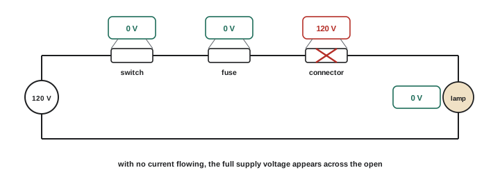
An open circuit breaks the current path: a blown fuse, a tripped breaker, a failed switch, a broken conductor, a loose or burnt termination, or a failed component in the load. The symptom is a load that does not operate, or a partial loss such as one phase missing on a three-phase motor (single phasing) or half the lights out on a multi-wire circuit. To find an open on an energized circuit, measure voltage at successive points from the source toward the load: voltage present across a closed switch should be near zero, while the full supply voltage appears across an open device, because no current flows and therefore no voltage is dropped elsewhere. The point where voltage to the reference disappears, or where full voltage appears across a component that should be closed, locates the open. On de-energized circuits, continuity tests between points find the break.
Open neutrals deserve special mention because they are dangerous. In a multi-wire branch circuit or a three-phase four-wire system, losing the neutral connection leaves loads on different phases in series across the line-to-line voltage. Voltages on lightly loaded phases rise and those on heavily loaded phases fall, damaging electronics and appliances and sometimes causing fires. Symptoms include lights brightening and dimming as loads switch, equipment failing on some circuits, and voltages to neutral that do not add up correctly. A lost service neutral can also put current onto water pipes and other bonded metal. Open neutrals require urgent attention.
Worked problem
Diagnosing an open neutral
In a house with a 120/240 V service, lights on some circuits glow brighter when a microwave runs and other lights dim. Measured voltages are L1–N 152 V, L2–N 88 V, L1–L2 240 V. What is the likely fault?
Show solution
- L1–L2 is normal at 240 V, so both lines are present.
- L1–N and L2–N should each be about 120 V and add to 240 V; here 152 + 88 = 240 V, but they are unbalanced.
- Unequal voltages that shift as loads change are the signature of an open or high-resistance neutral.
- The heavily loaded side (L2, with the microwave) drops, and the lightly loaded side rises.
- Check the neutral connections at the service, meter base and main panel; contact the utility if the service neutral is suspect, and turn off sensitive loads meanwhile.
Answer: An open or high-resistance neutral; locate and repair it urgently.
Short circuits and ground faults
A short circuit connects conductors of different potential through a low impedance, such as phase to phase or phase to neutral; a ground fault connects a phase conductor to ground or grounded metal. Both cause large currents that operate overcurrent devices, often with visible damage. When a breaker trips immediately on reset, a solid fault is likely; resetting repeatedly into a fault is dangerous and damages equipment, so the circuit should be tested before re-energizing. The method is to isolate and test: lock out the circuit, disconnect loads, and use an insulation tester or ohmmeter to check each conductor to the others and to ground. Then divide the circuit by opening junction points, testing each section until the faulted section is found. Common causes include damaged cables (nails, screws, rodents, crushing, abrasion), water in boxes, failed equipment insulation and wiring errors such as a neutral connected to a hot terminal.
Ground faults that do not trip overcurrent devices are harder to find. On ungrounded or high-resistance grounded systems (ELEC-320), a single ground fault does not trip anything but raises the voltage of the unfaulted phases to ground and must be located before a second fault causes a phase-to-phase short. Ground detector lights or monitoring relays indicate the faulted phase, and the fault is located by opening feeders one at a time, or with pulsing ground fault locators that inject a recognizable signal traced with a clamp sensor, avoiding a shutdown.
High-resistance connections
Loose, corroded, under-torqued or damaged connections are one of the most common causes of electrical fires and equipment failures. Unlike opens and shorts, they allow the circuit to work, at least for a while, while the joint heats. Power dissipated in the connection is the current squared times its resistance, so a connection with only 0.05 Ω of extra resistance carrying 100 A dissipates 500 W, enough to destroy insulation and terminals. Heat oxidizes the contact surfaces, increasing resistance further, a runaway process that ends in failure or fire. Aluminum conductors are especially susceptible if terminated without the correct connectors, torque and antioxidant compound.
Symptoms of high-resistance connections include flickering lights, equipment that resets or misbehaves under load, discolored or melted insulation, a burning smell, warm cover plates, voltage that sags under load, and hot spots on thermal images. Voltage drop testing and thermal imaging are the main tools for finding them.
Voltage drop testing
Voltage drop testing measures the voltage across conductors and connections while the circuit carries load. A good conductor or connection drops very little voltage; a bad one drops much more. The technique is to measure the voltage at the load under load, compare it with the voltage at the source, and then measure across individual segments: across each connection, along each conductor (from the panel terminal to the load terminal of the same conductor), and across switches and contacts. A closed contact should drop only millivolts; a reading of a volt or more across a contactor pole or breaker carrying normal current indicates a problem.
Worked problem
Locating a voltage drop
A 240 V, 30 A water heater circuit measures 240 V at the panel with no load, but only 222 V at the heater under load. Measurements under load: across the breaker 0.1 V, along L1 from panel to heater 1.4 V, along L2 6.8 V. Where is the problem?
Show solution
- Total drop = 240 − 222 = 18 V; part is in the supply, but the circuit conductors account for 0.1 + 1.4 + 6.8 V, plus a little across the other breaker pole.
- L1 drops 1.4 V at 30 A, which is reasonable for a long run (about 0.05 Ω).
- L2 drops 6.8 V at 30 A: about 0.23 Ω, nearly five times L1.
- Since L1 and L2 are the same size and length, the extra drop on L2 is in a connection: at the breaker, a splice or the heater terminal.
- Measure across each L2 connection under load; the one dropping several volts is the culprit, dissipating 30² × 0.18 ≈ 160 W.
Answer: A high-resistance connection on L2, dissipating roughly 160 W; find it by measuring across each L2 joint.
Thermal imaging for connection faults
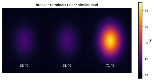
Thermal imaging finds high-resistance connections quickly and without contact, under normal load. Typical findings include hot breaker terminals, fuse clips, lugs, bus joints and contactor poles, and phase-to-phase temperature differences indicating imbalance or a failing component. Severity is usually judged by temperature rise over a reference, such as a similar component under similar load or the ambient temperature. NETA maintenance testing specifications suggest actions based on temperature difference between similar components under similar loading, for example 1 to 3 °C indicating a possible deficiency warranting investigation, 4 to 15 °C indicating probable deficiency to repair as time permits, and above 15 °C indicating a major discrepancy requiring immediate repair. Because temperature rise depends on load, readings taken at light load understate problems; correct for load or reinspect at higher load. Shiny metal surfaces reflect heat and have low emissivity, so readings should be taken on painted or insulated surfaces, or with emissivity corrections.
| Temperature difference (similar components, similar load) | Suggested interpretation | Action |
|---|---|---|
| 1–3 °C | Possible deficiency | Investigate; monitor |
| 4–15 °C | Probable deficiency | Repair as time permits |
| Above 15 °C | Major discrepancy | Repair immediately |
Faults in long and concealed cables
Faults in underground cables, long feeders and cables inside walls can be hard to locate. Techniques include time-domain reflectometry (TDR), which sends a pulse down the cable and times reflections from opens, shorts and impedance changes to estimate the distance to the fault; arc reflection and surge (thumper) methods for medium-voltage cables, which create a discharge at the fault that can be heard or detected above ground; tone generators and tracers for following cable routes and identifying conductors; and resistance bridge methods such as the Murray loop for low-resistance faults. On branch circuits in buildings, dividing the circuit at accessible boxes and testing each section is often fastest. Knowing where the cable runs, from drawings or tracing, comes first.
Arc-fault circuit interrupters and nuisance tripping
Arc-fault circuit interrupters (AFCIs) detect the electrical signatures of arcing in branch circuits, such as damaged cords, loose connections and pierced insulation, and trip before a fire starts. When AFCIs trip, the cause may be a genuine arcing fault, a wiring error such as a shared neutral between circuits, a neutral connected to the wrong circuit, or interaction with certain loads that produce arc-like noise, such as some motors and power supplies. Troubleshooting begins with any diagnostic indication the AFCI provides, which many models give by flashing codes or indicator lights after a trip. Next, disconnect loads and reconnect them one at a time to see whether a particular appliance causes the trip; check for shared or crossed neutrals with insulation testing between circuits; and inspect connections in boxes along the circuit, especially back-stabbed receptacle connections, which are a common source of real arcing. Replacing an AFCI with a standard breaker to stop nuisance tripping removes required protection and is not an acceptable fix.
Using the circuit's history
Before testing, ask how long the circuit has worked correctly and what has changed. A circuit that has always tripped occasionally suggests a design or load issue; one that started tripping after renovation suggests damage from new fasteners or a wiring change; one that trips only in wet weather suggests moisture in an outdoor box or underground run. Matching the pattern of symptoms to likely causes narrows the search before any meter is connected.
Checking terminations systematically
When a fault investigation reveals one failed termination, check others made at the same time or by the same method. Poor techniques, such as wrong torque, missing antioxidant on aluminum, damaged strands from incorrect stripping or using connectors outside their rated wire range, tend to repeat across a whole installation. A sample inspection or thermographic survey of similar connections can prevent several future failures.
Common mistakes
MistakeResetting a breaker repeatedly into a fault.
InsteadIsolate and test before re-energizing.
MistakeIgnoring unequal line-to-neutral voltages.
InsteadSuspect an open neutral and investigate urgently.
MistakeChecking connections only with power off.
InsteadUse voltage drop testing and thermography under load.
MistakeScanning shiny metal without emissivity correction.
InsteadMeasure painted or insulated surfaces or correct emissivity.
MistakeRetightening a burnt connection and leaving it.
InsteadReplace damaged terminals, lugs and conductors.
Summary and key terms
- Faults are opens, shorts, ground faults or high-resistance connections.
- Full supply voltage appears across an open in a series circuit.
- Open neutrals cause dangerous voltage shifts between phases.
- Shorts are found by isolating, testing insulation and dividing the circuit.
- High-resistance joints dissipate I²R heat and worsen over time.
- Voltage drop testing under load locates bad connections.
- Thermal imaging and TDR find hidden and developing faults.
- Open circuit
- A break in the current path.
- Short circuit
- Low-impedance connection between conductors.
- Ground fault
- Unintended connection from a phase to ground.
- Single phasing
- Loss of one phase to a three-phase load.
- Open neutral
- Loss of the neutral connection causing voltage imbalance.
- High-resistance connection
- Poor joint that heats under load.
- Voltage drop test
- Measuring drops across parts of a loaded circuit.
- Thermography
- Temperature imaging to find hot spots.
- TDR
- Time-domain reflectometry for locating cable faults.
- Ground fault locator
- Signal injection tool for tracing ground faults.
Practice problems
Work each problem on paper first, then reveal the answer to check.
What voltage appears across an open switch in a series circuit?
Show answer
The full supply voltage.
Name two symptoms of an open neutral.
Show answer
Lights brightening and dimming; unequal line-to-neutral voltages.
Why not reset a breaker repeatedly?
Show answer
It reapplies fault energy, causing damage and danger.
Power in a 0.1 Ω joint at 40 A?
Show answer
160 W.
How much voltage should a closed contactor pole drop?
Show answer
Millivolts.
Why scan under load?
Show answer
Heating depends on current.
A terminal is 20 °C hotter than its neighbors. Action?
Show answer
Repair immediately.
Why are shiny surfaces a problem for thermography?
Show answer
Low emissivity and reflections.
TDR pulse returns after 1 µs at 150 m/µs. Distance?
Show answer
75 m.
How are single ground faults found on ungrounded systems?
Show answer
Detector indications and pulsing locators or opening feeders.
Lesson quiz · 5 questions
Score 60% or more to complete this lesson.
Create a free account to save your progress, take quizzes and earn a certificate.