
ELEC-420 · Lesson 7 of 12 · 25 min
Power quality problems and how to find them
Some electrical problems are not failures of any single component but disturbances in the voltage or current itself. Computers reboot when the elevator starts, LED lights flicker, drives trip on overvoltage at the same time every morning, transformers run hot at half load, neutral conductors overheat, and capacitor banks fail repeatedly. These are power quality problems. Diagnosing them requires understanding the types of disturbance, where they come from, how to measure them with power quality analyzers, and which remedies work. This lesson covers voltage sags and swells, interruptions, transients, harmonics, flicker, imbalance and power factor, along with a practical approach to power quality investigations.
What power quality means
An ideal supply is a perfect sine wave at constant amplitude and frequency, balanced across three phases, with no interruptions. Real supplies deviate from this ideal, and loads also distort the current they draw, which in turn distorts the voltage. Standards such as IEEE 1159 (monitoring power quality), IEEE 519 (harmonic limits), CSA C61000 and IEC 61000 series and EN 50160 describe the types of disturbances and acceptable levels. A power quality problem exists when a disturbance causes equipment to malfunction, fail or wear prematurely. Studies consistently find that most power quality problems originate inside the customer's facility, from its own loads and wiring, rather than from the utility, although utility events such as faults on the distribution system cause many sags.
Voltage sags, swells and interruptions
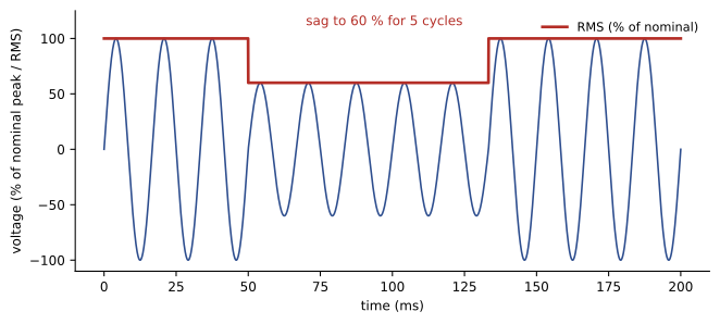
A sag (dip) is a short reduction in RMS voltage, typically to between 10 % and 90 % of nominal for half a cycle to a minute. Sags are the most common disturbance affecting industrial equipment. They are caused by faults on the utility system or in the facility, often far away, and by starting large motors. Sensitive equipment such as drives, PLCs, contactors and computers can trip or drop out during sags lasting only a few cycles; a contactor coil may drop out when voltage falls below about 70 % for a cycle or two. A swell is a short increase in voltage, often caused by single-line-to-ground faults raising the voltage on unfaulted phases or by switching off large loads. Interruptions are complete losses of voltage, momentary (from utility reclosers clearing temporary faults) or sustained.
Remedies depend on the cause and duration: staggering or soft-starting large motors; ride-through settings in drives (allowing them to continue through short sags using DC bus energy); powering control circuits from uninterruptible power supplies, constant-voltage transformers or DC supplies; and specifying equipment that meets sag immunity standards such as SEMI F47, which requires semiconductor equipment to ride through sags to 50 % for 200 ms, 70 % for 0.5 s and 80 % for 1 s.
Transients
Transients are very short, high-magnitude disturbances lasting microseconds to milliseconds. Impulsive transients come from lightning and from switching inductive loads; oscillatory transients come from switching capacitor banks, which can briefly double the voltage. Transients damage insulation and electronic components, cause equipment to lock up or reset, and degrade surge protective devices over time. Remedies include surge protective devices (SPDs) in a coordinated scheme at the service entrance, distribution panels and sensitive equipment, good grounding and bonding to keep equipment at a common potential, and controlled switching or detuning reactors for capacitor banks. Because transients are so short, they require analyzers with fast sampling to capture.
Harmonics
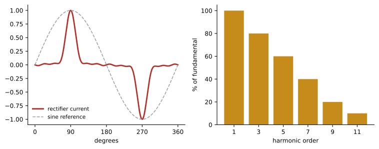
Non-linear loads, such as VFDs, computers, LED drivers, battery chargers, UPS systems and EV chargers, draw current in pulses rather than smooth sine waves. Mathematically, these distorted currents consist of the fundamental frequency (60 Hz in North America) plus harmonics at integer multiples: 180 Hz (3rd), 300 Hz (5th), 420 Hz (7th) and so on. Total harmonic distortion (THD) measures the combined harmonic content relative to the fundamental:
Harmonic currents cause several problems. They add heating in transformers, conductors and motors beyond what the RMS current suggests, because losses increase with frequency; transformers serving non-linear loads may need derating or K-rated designs. Triplen harmonics (3rd, 9th, 15th) from single-phase non-linear loads add in the neutral of a three-phase four-wire system instead of canceling, so the neutral can carry more current than the phase conductors, up to about 1.7 times phase current in extreme cases, overheating neutrals that were sized for balanced linear loads. Harmonic currents flowing through system impedance distort the voltage, which can upset other equipment. And harmonics can resonate with power factor correction capacitors, amplifying currents and destroying capacitors.
IEEE 519 sets limits on current distortion at the point of common coupling with the utility, depending on the ratio of short-circuit current to load current, and limits on voltage distortion, which for systems up to 1 kV are 8 % total harmonic distortion and 5 % for any individual harmonic. Remedies include line reactors and DC chokes on drives, multi-pulse drives (12- or 18-pulse), active front-end drives, passive harmonic filters, active harmonic filters that inject canceling currents, oversized or separate neutrals, and K-rated or harmonic-mitigating transformers.
Worked problem
Neutral current from triplen harmonics
A three-phase, four-wire panel serves office computers. Each phase carries 100 A RMS, consisting of a fundamental of 85 A and a 3rd harmonic of 50 A, with other harmonics small. Estimate the neutral current.
Show solution
- Balanced fundamental currents cancel in the neutral.
- Third harmonic currents are in phase on all three phases, so they add: 3 × 50 = 150 A.
- Neutral current ≈ 150 A, compared with 100 A on each phase.
- A neutral sized equal to the phase conductors would be overloaded by 50 %.
- Use a double-sized neutral, separate neutrals, or harmonic mitigation; verify with a true RMS clamp meter on the neutral.
Answer: About 150 A in the neutral, 1.5 times the phase current.
Flicker, imbalance and power factor
Flicker is the visible fluctuation of lighting caused by rapid voltage variations, from loads such as arc furnaces, welders, large motors starting frequently or fluctuating PV output. It is measured with flickermeters as short-term (Pst) and long-term (Plt) severity indices. LED lamps vary greatly in their sensitivity to voltage fluctuations, so flicker complaints sometimes increase after lighting retrofits. Voltage imbalance, discussed in Lesson 6 for motors, arises from unevenly distributed single-phase loads, high-resistance connections on one phase, or utility conditions. Power factor is the ratio of real power to apparent power; low displacement power factor from induction motors increases current and losses and may incur utility penalties, while distortion from harmonics also lowers true power factor. Power factor correction capacitors improve displacement power factor but must be applied carefully where harmonics are present, often with detuning reactors.
| Disturbance | Typical causes | Typical effects | Common remedies |
|---|---|---|---|
| Sag | Faults, motor starting | Drive and contactor dropouts, resets | Ride-through, UPS, soft starters |
| Swell | Ground faults, load rejection | Electronics stress | SPDs, regulation |
| Interruption | Utility reclosing, faults | Shutdowns, data loss | UPS, standby generation |
| Transient | Lightning, capacitor switching | Insulation and electronic damage | Coordinated SPDs, grounding |
| Harmonics | VFDs, electronics, chargers | Heating, neutral overload, resonance | Reactors, filters, K-rated transformers |
| Flicker | Arc furnaces, welders, fluctuating loads | Visible lighting fluctuation | Separate feeders, compensation |
| Imbalance | Uneven single-phase loads, bad connections | Motor heating, neutral current | Rebalance loads, repair connections |
Investigating power quality problems
A structured investigation follows the troubleshooting method of Lesson 1:
- Define the problem precisely: which equipment malfunctions, how, when and how often.
- Inspect the installation: grounding and bonding, neutral sizing, loose connections, shared circuits between sensitive and disturbing loads.
- Measure: install a power quality analyzer meeting IEC 61000-4-30 Class A or S at the affected equipment and, if needed, at the service, recording voltage and current on all phases and neutral for at least a full business cycle, typically a week, with event triggers set to capture sags, swells and transients.
- Correlate: compare recorded events with the times of equipment problems; check whether disturbances originate inside or outside (for example, a sag accompanied by a current increase on the monitored circuit originates downstream; one with no current change likely originates upstream).
- Remedy and verify: apply the most targeted, cost-effective fix and monitor again to confirm improvement.
Analyzers must be installed safely, by qualified people with appropriate PPE, using voltage leads with fused connections and current probes of suitable range. Recording neutral-to-ground voltage alongside phase voltages helps identify wiring and grounding problems.
Grounding and wiring problems that look like power quality issues
Many complaints attributed to power quality are actually wiring and grounding problems. Loose neutral connections cause voltage fluctuations and imbalance; shared neutrals between circuits carry unexpected current; improper neutral-to-ground bonds create objectionable current and noise on grounding conductors; and isolated ground receptacles installed incorrectly can create ground loops. Data and communication equipment is particularly sensitive to differences in ground potential between devices connected by data cables. Measuring neutral-to-ground voltage at sensitive loads is a useful first check: values above a few volts under load suggest neutral problems, undersized neutrals or excessive neutral current. Correcting the wiring often solves the problem without any specialized power conditioning equipment.
Surge protection in practice
Surge protective devices are installed in a coordinated scheme: a Type 1 or Type 2 device at the service entrance diverts large external surges, Type 2 devices at distribution and branch panels limit residual and internally generated surges, and point-of-use devices protect individual sensitive equipment. SPDs are most effective with short, straight connecting leads, because lead inductance adds voltage during fast surges; every 30 cm of lead can add tens to hundreds of volts to the let-through voltage. SPDs wear out as they absorb surges, so their status indicators should be checked during maintenance, and failed units replaced. Grounding and bonding must be sound for SPDs to work, because they divert surge current to ground.
Monitoring permanently
Facilities with critical loads, such as data centers, hospitals and manufacturing plants, increasingly install permanent power quality monitoring at the service and key distribution points. Permanent monitors capture events as they happen, so there is no need to wait for a problem to recur after installing a portable analyzer, and they build a long-term record of supply performance useful in discussions with the utility. Software can correlate events across many meters, showing where a disturbance originated and how it propagated through the system.
Working with the utility
When measurements show that disturbances originate on the utility supply, such as frequent sags from faults on the distribution system or sustained voltage outside the permitted range, the facility should share the data with the utility. Utilities can sometimes identify the cause, such as a failing component, tree contact or a nearby customer's equipment, and correct it. Utility voltage ranges are defined in standards and supply agreements: in Canada, CSA C235 sets preferred voltage ranges, and in the United States, ANSI C84.1 does. Data recorded with a Class A analyzer carries more weight in such discussions.
Recording a baseline
As with other troubleshooting, a baseline helps. Recording power quality at the service and key panels when a facility is commissioned, or before major new loads are added, provides reference values for voltage, harmonics, imbalance and flicker. When complaints arise later, new measurements can be compared with the baseline to see what has changed, such as harmonic distortion increasing after a large number of drives or EV chargers were installed, and to plan corrective measures before problems become severe.
Power quality work also benefits from teamwork between electricians, engineers and equipment suppliers. Electricians see symptoms first and install the instruments; engineers analyze data and design remedies; suppliers know how their equipment responds to disturbances and which settings improve ride-through. Bringing them together early shortens investigations.
Common mistakes
MistakeBlaming the utility without measuring.
InsteadRecord and correlate; most problems originate on site.
MistakeSizing neutrals for linear loads only.
InsteadAccount for triplen harmonics with non-linear loads.
MistakeAdding power factor capacitors without a harmonic study.
InsteadCheck for resonance and use detuned banks.
MistakeMonitoring for an hour.
InsteadRecord at least a full operating cycle, often a week.
MistakeUsing non-true-RMS meters on distorted circuits.
InsteadUse true RMS instruments and analyzers.
Summary and key terms
- Power quality problems are disturbances in voltage or current that upset equipment.
- Sags are the most common disturbance; ride-through and UPS help.
- Transients need coordinated SPDs and good grounding.
- Non-linear loads create harmonics measured by THD.
- Triplen harmonics add in the neutral and can overload it.
- Flicker, imbalance and power factor also affect equipment and costs.
- Investigate with analyzers over a full operating cycle and correlate events.
- Power quality
- How closely supply matches an ideal sine wave.
- Sag
- Short reduction in RMS voltage.
- Swell
- Short increase in RMS voltage.
- Transient
- Very short high-magnitude disturbance.
- Harmonic
- Frequency component at a multiple of the fundamental.
- THD
- Total harmonic distortion.
- Triplen harmonics
- Odd multiples of the 3rd harmonic that add in neutrals.
- K-rated transformer
- Transformer designed for harmonic heating.
- Flicker
- Visible lighting fluctuation from voltage variation.
- SPD
- Surge protective device.
Practice problems
Work each problem on paper first, then reveal the answer to check.
What range of voltage defines a sag?
Show answer
About 10 % to 90 % of nominal.
Name two causes of sags.
Show answer
Utility faults, large motor starting.
What does SEMI F47 specify?
Show answer
Sag ride-through for semiconductor equipment.
What frequency is the 5th harmonic on a 60 Hz system?
Show answer
300 Hz.
Fundamental 50 A, 3rd 20 A, 5th 15 A. THD?
Show answer
√(400+225)/50 = 50 %.
Why do triplen harmonics overload neutrals?
Show answer
They are in phase and add.
Name two harmonic remedies.
Show answer
Line reactors, filters, multi-pulse drives, K-rated transformers.
Why can capacitors fail with harmonics?
Show answer
Resonance amplifies harmonic currents.
How long should an analyzer record?
Show answer
A full operating cycle, often a week.
A sag with rising local current originates where?
Show answer
Downstream, within the monitored circuit.
Lesson quiz · 5 questions
Score 60% or more to complete this lesson.
Create a free account to save your progress, take quizzes and earn a certificate.