
ELEC-420 · Lesson 11 of 12 · 27 min
Acceptance testing of switchgear, breakers, transformers and cables
Large electrical distribution equipment, such as switchgear, circuit breakers, protective relays, transformers and medium-voltage cables, is tested before it is placed in service, because a failure at first energization or during the first fault can be catastrophic and expensive. Acceptance testing verifies that equipment was not damaged in shipping or installation, is assembled and connected correctly, and will operate as designed. Electricians often perform or assist with these tests, and specialized testing firms use detailed procedures such as the ANSI/NETA Acceptance Testing Specifications (ATS). This lesson describes the main tests for each type of equipment, what they reveal and how results are evaluated.
Acceptance testing principles
Acceptance tests combine visual and mechanical inspection with electrical tests. Visual and mechanical inspection checks nameplate data against drawings, physical damage, anchoring, alignment, grounding, cleanliness, correct lubrication, mechanical operation of breakers and interlocks, and torque of bolted connections, often verified with a calibrated torque wrench or by micro-ohmmeter readings. Electrical tests measure insulation, resistance of current paths, ratios, timing and protective functions. Results are compared with manufacturer data, standards, previous tests and similar equipment. A test report records the equipment, test conditions (temperature, humidity), instruments with calibration dates, readings and conclusions, and becomes the baseline for future maintenance testing. NETA tables give guidance values, such as minimum insulation resistance by voltage class and allowable deviations between phases.
Switchgear and busway
Tests on switchgear, switchboards and busway typically include:
- Insulation resistance of each bus phase to ground and phase to phase, with instrument transformers and surge arresters disconnected as required.
- Contact or joint resistance of bus connections with a micro-ohmmeter, comparing similar joints; deviations greater than about 50 % from the lowest value warrant investigation.
- Dielectric withstand (hipot) tests at specified voltages for medium-voltage switchgear.
- Verification of control wiring, interlocks (such as key interlocks preventing paralleling of sources), mechanical operation of draw-out mechanisms and racking.
- Functional testing of metering, indicating lights, heaters and ventilation.
Foreign objects left in switchgear, such as tools, hardware and packaging, are a notorious cause of failures at energization, so a final inspection immediately before closing covers is essential.
Low-voltage circuit breakers
Molded-case breakers are typically inspected and tested for insulation resistance and, for larger or adjustable-trip units, contact resistance and trip performance. Power circuit breakers and insulated-case breakers with electronic trip units receive more thorough testing:
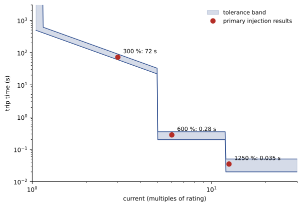
- Primary current injection: a high-current test set passes current through the breaker's main contacts, simulating overloads, short circuits and ground faults, and measures trip times against the time–current curve. This tests the complete system: current sensors, trip unit and mechanism.
- Secondary injection: a test set injects signals directly into the electronic trip unit, verifying its settings and timing but not the current sensors.
- Contact resistance of each pole, compared with the manufacturer's values and between poles.
- Insulation resistance across open contacts, pole to pole and pole to ground.
- Mechanical operation, including closing and opening, charging motors, shunt trips, undervoltage releases and auxiliary contacts.
Trip unit settings must match the coordination study, and the as-left settings are recorded. Breakers whose trip times fall outside the manufacturer's tolerance band are repaired or replaced.
Worked problem
Evaluating a primary injection test
An 800 A breaker with long-time pickup set at 1.0 × (800 A) and a long-time delay giving 60 to 90 s at 300 % is tested with 2,400 A primary injection. It trips in 125 s. Is it acceptable?
Show solution
- Test current: 2,400 A = 300 % of 800 A.
- Expected trip time band: 60 to 90 s.
- Measured 125 s exceeds the upper limit by 35 s.
- The breaker would allow an overload to persist longer than coordinated, risking conductor damage and affecting selectivity.
- Verify settings and the test set connections, retest, and repair or replace the trip unit or breaker if it remains out of tolerance.
Answer: No; 125 s is outside the 60–90 s band, so the breaker fails and must be investigated.
Protective relays
Medium-voltage and large low-voltage systems use protective relays, now mostly microprocessor-based, that operate breakers on overcurrent, ground fault, differential, under- and overvoltage, frequency and other conditions. Relay testing verifies that the settings entered match the approved settings file, that the relay operates at the correct pickup and timing when test currents and voltages are injected from a relay test set, that the outputs actually trip the intended breaker (trip checks), and that current and voltage transformer wiring, polarity and ratios are correct. Errors in CT polarity or ratio are a common cause of relay misoperation, so in-service checks with load current, comparing measured phase angles and magnitudes, confirm correct wiring after energization. Settings files, firmware versions and test results are kept under strict configuration control.
Instrument transformers
Current transformers (CTs) and voltage transformers (VTs) supply metering and protection. Tests include ratio and polarity verification, insulation resistance, excitation (saturation) curves for protection CTs, burden measurements and checks that CT secondaries are shorted or connected before energizing. An open-circuited CT secondary under load develops dangerously high voltages and can destroy the CT and injure people, so CT shorting blocks must be used whenever meters or relays are disconnected.
Transformers
Distribution and power transformers receive tests that reveal damage, wiring errors and insulation problems:
- Insulation resistance of windings to ground and between windings, with polarization index for larger units.
- Turns ratio (TTR) test on each tap position, comparing measured ratio with nameplate; deviations should generally be within 0.5 % of calculated values. Ratio errors indicate shorted turns or incorrect tap connections.
- Winding resistance on each tap, compared between phases and with factory values, revealing loose connections, broken strands and tap changer problems.
- Polarity and vector group (phase displacement) verification.
- Excitation current, which can reveal core and winding problems.
- For liquid-filled transformers, insulating oil tests (dielectric strength, moisture, acidity) and dissolved gas analysis, which detects internal arcing and overheating from the gases they produce.
- Power factor or dissipation factor (tan delta) tests of insulation for larger and medium-voltage units.
Before energizing, verify tap settings are correct for the supply voltage, that neutral and ground connections match the design (ELEC-320), and that temperature monitoring and alarms work.
Worked problem
Checking a turns ratio test
A 12,470 V delta to 480Y/277 V transformer is on its nominal tap. The TTR test on one phase measures 45.12 (high-voltage winding to the low-voltage phase-to-neutral winding). Is it within 0.5 %?
Show solution
- For delta–wye, each HV winding (12,470 V) corresponds to one LV phase-to-neutral winding (277 V).
- Calculated ratio = 12,470 / 277 = 45.02.
- Deviation = (45.12 − 45.02) / 45.02 × 100 = +0.22 %.
- The deviation is within ±0.5 %, so this phase passes.
- Repeat for the other phases and all tap positions, and compare phases with each other.
Answer: Yes, +0.22 % is within 0.5 %.
Medium-voltage cables
Medium-voltage cables and their terminations and splices are tested after installation because damage during pulling and poor workmanship on accessories are common causes of early failure. Tests include insulation resistance (shield to conductor), shield continuity, and withstand testing. For extruded polymeric cables (XLPE, EPR), very low frequency (VLF) AC withstand testing at about 0.1 Hz is now preferred over high DC hipot testing, which can accelerate failure of aged polymeric insulation. Diagnostic tests assess condition: tan delta (dissipation factor) testing measures insulation losses, with increasing values or instability indicating water treeing or contamination; partial discharge testing detects small discharges at voids and defects in terminations and splices, locating them along the cable. IEEE 400 and its parts describe these methods. Terminations and splices must be made by qualified, often certified, installers following the manufacturer's instructions precisely.
| Equipment | Key acceptance tests | What they reveal |
|---|---|---|
| Switchgear and bus | IR, joint resistance, hipot, interlocks | Insulation, loose joints, assembly errors |
| Power circuit breakers | Primary injection, contact resistance, IR, mechanism | Trip accuracy, contact wear, mechanical faults |
| Protective relays | Settings, injection, trip checks, CT/VT wiring | Wrong settings, wiring and polarity errors |
| Transformers | IR, TTR, winding resistance, oil and DGA, power factor | Shorted turns, connection faults, insulation |
| MV cables | IR, VLF withstand, tan delta, partial discharge | Installation damage, defective accessories |
| Instrument transformers | Ratio, polarity, excitation, IR | Wiring and saturation problems |
Testing ground-fault protection and interlocks in switchgear
Switchgear acceptance testing also covers system functions. Ground-fault protection systems are tested by primary injection through each sensor to confirm pickup and timing, and by checking that neutral sensors are installed with correct polarity so that normal neutral current does not cause false trips. Zone-selective interlocking, which lets downstream breakers restrain upstream breakers during faults to improve both coordination and arc flash performance, is tested by simulating faults at different locations and confirming the correct breaker trips with the correct delay. Key interlocks and electrical interlocks that prevent paralleling of sources, closing onto grounded bus or opening doors on energized compartments are operated to confirm they work. Automatic transfer schemes in double-ended switchgear, with main–tie–main arrangements, are tested through every transfer sequence.
Arc flash mitigation devices
Many modern installations include arc flash mitigation features: maintenance mode switches that temporarily set breakers to instantaneous trip while people work nearby, arc flash relays that detect the light of an arc and trip upstream devices within milliseconds, and arc-resistant switchgear that directs arc energy away from operators. These features must be tested to confirm they operate as designed: maintenance switches are checked for correct pickup and indication, arc flash relay sensors are tested with a light source and the trip path verified, and arc-resistant equipment is inspected to confirm that vent paths and plenums are installed correctly and that doors and covers are secured as the rating requires.
Test reports and acceptance
At the end of acceptance testing, the testing organization issues a report summarizing every item tested, the results, deficiencies found and their correction, and a statement of whether the equipment is suitable for energization. Items that failed must be corrected and retested before energization; items with marginal results may be accepted with a recommendation for follow-up. The report becomes part of the turnover documents and the baseline for the maintenance program, so accuracy and completeness are essential. Owners increasingly require that testing be performed by firms or technicians certified under programs such as NETA certification, which demonstrates competence in these specialized tests.
Safety during acceptance testing
Acceptance testing involves high test voltages, high test currents and work near equipment that may be connected to energized sources. Test areas are barricaded, equipment under test is isolated and locked out from all sources, temporary grounds are applied and removed under control, and test sets are positioned so that operators are outside the hazard area. Communication between team members during switching and testing is formal and clear. Many incidents during testing involve unexpected backfeeds through control power, instrument transformers or interconnected systems, so isolation is verified thoroughly.
Infrared and visual inspection at acceptance
A final element of acceptance testing is an infrared survey after the equipment has been energized and loaded, typically within the first weeks of operation, to catch any connection that passed static tests but heats under real current. Combined with a visual inspection of indicators, ventilation and alarms during normal operation, this closes the gap between de-energized tests and in-service performance, and establishes the thermal baseline for future maintenance surveys.
Accurate acceptance test records also support future arc flash studies and coordination reviews, because they confirm the settings and condition of each protective device at the time of energization.
Common mistakes
MistakeRelying only on secondary injection of breakers.
InsteadUse primary injection to test sensors and mechanism too.
MistakeLeaving CT secondaries open.
InsteadShort or connect CT secondaries before energizing.
MistakeEnergizing a transformer on the wrong tap.
InsteadVerify tap position and ratio before energizing.
MistakeUsing high DC hipot on aged polymeric MV cable.
InsteadUse VLF withstand and diagnostic tests.
MistakeAccepting relay settings without comparing to the approved file.
InsteadVerify settings, firmware and trip outputs.
Summary and key terms
- Acceptance testing verifies equipment before service and creates a baseline.
- Inspection, torque and joint resistance checks find assembly problems.
- Primary injection tests the complete breaker trip system.
- Relays need settings verification, injection testing and trip checks.
- CT secondaries must never be open-circuited under load.
- Transformer tests include TTR, winding resistance, IR and oil analysis.
- MV cables are tested with VLF, tan delta and partial discharge methods.
- Acceptance testing
- Testing new equipment before it is placed in service.
- NETA ATS
- Acceptance Testing Specifications for electrical equipment.
- Primary injection
- Testing a breaker with high current through its contacts.
- Secondary injection
- Testing a trip unit with injected signals.
- Protective relay
- Device detecting abnormal conditions and tripping breakers.
- Current transformer
- Transformer supplying current to meters and relays.
- TTR
- Transformer turns ratio test.
- Dissolved gas analysis
- Oil test detecting internal faults by gases.
- Tan delta
- Dissipation factor measuring insulation losses.
- Partial discharge
- Small electrical discharges in insulation defects.
Practice problems
Work each problem on paper first, then reveal the answer to check.
What does acceptance testing verify?
Show answer
No damage, correct assembly and correct operation.
Why compare bus joint resistances?
Show answer
A much higher joint indicates a poor connection.
What does primary injection test that secondary does not?
Show answer
Current sensors and the full trip path.
Why are relay trip checks needed?
Show answer
To confirm the relay actually opens the breaker.
Why is an open CT secondary dangerous?
Show answer
It develops very high voltages.
Typical TTR tolerance?
Show answer
Within 0.5 % of calculated.
What does winding resistance reveal?
Show answer
Loose connections, broken strands, tap changer problems.
What does dissolved gas analysis detect?
Show answer
Internal arcing and overheating.
Why prefer VLF for polymeric cable?
Show answer
High DC can damage aged insulation.
What does partial discharge testing find?
Show answer
Defects in insulation, terminations and splices.
Lesson quiz · 5 questions
Score 60% or more to complete this lesson.
Create a free account to save your progress, take quizzes and earn a certificate.