
CMPUT-411 · Lesson 4 of 12 · 34 min
Rotations, quaternions and cameras
Rotation is the hardest of the basic transformations to handle well. Positions and scales can be added and averaged component by component, but orientations cannot: the set of 3D rotations is curved, and every way of describing it with a few numbers has drawbacks. Graphics needs rotations for objects, for skeletal animation and above all for cameras, which must be pointed, orbited, flown and interpolated smoothly. This lesson compares the main representations, rotation matrices, Euler angles, axis-angle and quaternions, explains gimbal lock and spherical interpolation, and then builds the camera's view matrix. ROB-210 (lesson 3) treats the same representations for robot kinematics; our emphasis is on interpolation and cameras.
Rotation matrices
A 3D rotation is a 3 by 3 orthogonal matrix with determinant +1. Its columns are the images of the x, y and z axes and form an orthonormal, right-handed basis. Rotation matrices compose by multiplication, rotate vectors directly and invert by transposition, which is why GPUs and renderers ultimately use them. But they store nine numbers for three degrees of freedom; they drift away from orthogonality under repeated floating-point multiplication; and they cannot be interpolated directly: averaging two rotation matrices element by element generally gives a matrix that is not a rotation and may shrink or skew the object.
Graphics systems differ in handedness and in which axis is up. OpenGL's traditional conventions and most modeling tools use a right-handed system with y up and the camera looking down the negative z axis; Direct3D traditionally used left-handed coordinates; Blender, Unreal Engine and many CAD systems treat z as up. Positive rotation follows the right-hand rule in a right-handed system: with the thumb along the axis, fingers curl in the positive direction. Converting assets between tools with different conventions is a frequent source of objects lying on their sides or mirrored.
Euler angles and gimbal lock
Euler angles describe an orientation as three successive rotations about coordinate axes, such as yaw about the vertical axis, pitch about the side axis and roll about the forward axis. They are compact and intuitive, which is why animation software exposes them and why aircraft and vehicles are described with them. But there are twelve valid axis orders (XYZ, ZYX, ZXZ and so on), and the same three numbers mean different orientations in different orders, so every tool must state its convention.
The deeper problem is gimbal lock. With yaw-pitch-roll angles, when the pitch is 90 degrees, the first and last rotation axes line up, and changing yaw has exactly the same effect as changing roll. One degree of freedom is lost: the orientation depends only on the difference between yaw and roll, and there is no small change of the three angles that produces a rotation about the lost axis. The name comes from mechanical gimbals, nested rings that hold a gyroscope, which physically lock when two rings become coplanar; the Apollo guidance system famously had to avoid the gimbal lock orientation.
# Gimbal lock: with yaw-pitch-roll Euler angles, a pitch of 90 degrees makes
# yaw and roll rotate about the same axis, so one degree of freedom is lost.
import numpy as np
def Rx(a): c, s = np.cos(a), np.sin(a); return np.array([[1, 0, 0], [0, c, -s], [0, s, c]])
def Ry(a): c, s = np.cos(a), np.sin(a); return np.array([[c, 0, s], [0, 1, 0], [-s, 0, c]])
def Rz(a): c, s = np.cos(a), np.sin(a); return np.array([[c, -s, 0], [s, c, 0], [0, 0, 1]])
def euler(yaw, pitch, roll):          # R = Rz(yaw) Ry(pitch) Rx(roll), angles in degrees
    y, p, r = np.radians([yaw, pitch, roll])
    return Rz(y) @ Ry(p) @ Rx(r)
A = euler(30, 90, 0)
B = euler(0, 90, -30)                 # different angles ...
C = euler(50, 90, 20)                 # ... and another pair with the same difference
print("yaw 30, roll 0  equals yaw 0, roll -30 at pitch 90:", np.allclose(A, B))
print("yaw 50, roll 20 equals them too (only yaw - roll matters):", np.allclose(A, C))
# Away from 90 degrees the same angle changes give different orientations
print("at pitch 45 the two settings differ:", not np.allclose(euler(30, 45, 0), euler(0, 45, -30)))yaw 30, roll 0 equals yaw 0, roll -30 at pitch 90: True yaw 50, roll 20 equals them too (only yaw - roll matters): True at pitch 45 the two settings differ: True
At a pitch of 90 degrees, quite different yaw and roll values produce identical matrices, because only their difference matters. Near this singularity, small orientation changes can require huge angle changes, which makes animation curves jump and cameras spin wildly. Euler angles also interpolate poorly: interpolating each angle independently follows a path that is not the shortest rotation, can wobble and depends on the axis order. Euler angles are fine for user-facing controls with limited ranges, such as a first-person camera whose pitch is clamped below 90 degrees, but internal orientation state should use a better representation.
Axis-angle and Rodrigues' formula
Euler's rotation theorem states that any 3D rotation is a single rotation by some angle \(\theta\) about some unit axis \(\hat{k}\). The axis-angle representation stores exactly that, often as a single rotation vector \(\theta \hat{k}\) whose direction is the axis and whose length is the angle. Rodrigues' rotation formula rotates a vector \(v\) directly:
Axis-angle is natural for describing angular velocity, for physics engines and for specifying a single rotation, but composing two axis-angle rotations has no simple formula, and interpolation is awkward. Quaternions package axis-angle in a form that composes and interpolates well.
Quaternions
William Rowan Hamilton discovered quaternions in 1843, famously carving the defining relation \(i^2 = j^2 = k^2 = ijk = -1\) into a bridge in Dublin. A quaternion has a scalar part and a three-dimensional vector part, \(q = w + xi + yj + zk\), written \((w, \mathbf{v})\). Ken Shoemake's 1985 SIGGRAPH paper 'Animating rotation with quaternion curves' introduced them to computer graphics, and they are now the standard internal representation of orientation in game engines, animation systems and robotics. A rotation by angle \(\theta\) about unit axis \(\hat{k}\) is represented by the unit quaternion
To rotate a vector \(v\), treat it as a pure quaternion \((0, v)\) and compute \(q\,v\,q^{*}\), where \(q^{*} = (w, -\mathbf{v})\) is the conjugate, which equals the inverse for a unit quaternion. Composition is quaternion multiplication: applying \(q_1\) then \(q_2\) is \(q_2 q_1\), the same order convention as matrices. Quaternion multiplication is not commutative, matching rotations. A unit quaternion uses four numbers for three degrees of freedom, with the single constraint of unit length, which is easy to restore by normalizing. The half angle has a curious consequence: \(q\) and \(-q\) represent the same rotation, because rotating by \(\theta + 360°\) changes the half-angle by 180 degrees. Unit quaternions double-cover the rotations.
| Representation | Numbers stored | Strengths | Weaknesses |
|---|---|---|---|
| Rotation matrix | 9 | Fast to apply; GPUs use it directly; composition by multiplication | Redundant; drifts from orthogonality; cannot be interpolated directly |
| Euler angles | 3 | Compact; intuitive for people and limited ranges | Twelve conventions; gimbal lock; poor interpolation |
| Axis-angle (rotation vector) | 3 or 4 | Geometric meaning; angular velocity | Composition and interpolation awkward |
| Unit quaternion | 4 | No gimbal lock; cheap composition; smooth interpolation by slerp | Less intuitive; double cover requires care |
Interpolating orientations: slerp
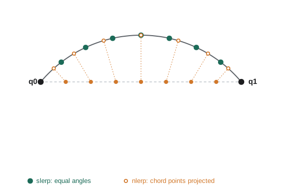
Animation needs smooth transitions between orientations: a camera turning from one view to another, a character's joint moving between keyframes. Unit quaternions live on the unit sphere in four dimensions, and the natural interpolation follows the great-circle arc between two of them at constant angular speed. Shoemake called this spherical linear interpolation, or slerp:
Because \(q\) and \(-q\) are the same rotation, an implementation first checks the sign of the dot product and negates one quaternion if it is negative, so that the interpolation takes the shorter of the two possible arcs. When the quaternions are nearly equal, \(\sin\Omega\) approaches zero, and implementations switch to normalized linear interpolation, nlerp: interpolate the four components linearly and renormalize. Nlerp follows the same path as slerp but at slightly non-uniform speed, faster in the middle, and it is cheaper and commutative, which makes it popular for blending several animations at once.
# Quaternions: rotating vectors, composing rotations and slerp.
import numpy as np
def q_axis_angle(axis, deg):
    axis = np.asarray(axis, float) / np.linalg.norm(axis)
    h = np.radians(deg) / 2
    return np.concatenate([[np.cos(h)], np.sin(h) * axis])      # (w, x, y, z)
def q_mul(a, b):
    w1, x1, y1, z1 = a; w2, x2, y2, z2 = b
    return np.array([w1*w2 - x1*x2 - y1*y2 - z1*z2,
                     w1*x2 + x1*w2 + y1*z2 - z1*y2,
                     w1*y2 - x1*z2 + y1*w2 + z1*x2,
                     w1*z2 + x1*y2 - y1*x2 + z1*w2])
def q_conj(q): return q * np.array([1, -1, -1, -1])
def rotate(q, v): return q_mul(q_mul(q, np.concatenate([[0], v])), q_conj(q))[1:]
def slerp(a, b, t):
    d = np.dot(a, b)
    if d < 0: b, d = -b, -d                       # take the shorter arc
    if d > 0.9995: r = a + t * (b - a); return r / np.linalg.norm(r)
    th = np.arccos(d)
    return (np.sin((1 - t) * th) * a + np.sin(t * th) * b) / np.sin(th)
qz = q_axis_angle([0, 0, 1], 90)
print("rotate x axis 90 deg about z:", np.round(rotate(qz, [1, 0, 0]), 3))
qx = q_axis_angle([1, 0, 0], 90)
both = q_mul(qx, qz)                              # qz first, then qx
print("z then x applied to x axis:", np.round(rotate(both, [1, 0, 0]), 3))
a, b = q_axis_angle([0, 0, 1], 0), q_axis_angle([0, 1, 0], 120)
print(" t   slerp angle  nlerp angle   (degrees from start)")
for t in (0.25, 0.5, 0.75):
    s = slerp(a, b, t)
    n = (1 - t) * a + t * b; n /= np.linalg.norm(n)
    ang = lambda q: np.degrees(2 * np.arccos(min(1, abs(q[0]))))
    print(f"{t:4} {ang(s):10.1f} {ang(n):12.1f}")
print("q and -q rotate identically:", np.allclose(rotate(qz, [0.3, 0.2, 0.9]), rotate(-qz, [0.3, 0.2, 0.9])))rotate x axis 90 deg about z: [0. 1. 0.] z then x applied to x axis: [0. 0. 1.] t slerp angle nlerp angle (degrees from start) 0.25 30.0 27.8 0.5 60.0 60.0 0.75 90.0 92.2 q and -q rotate identically: True
The quaternion for 90 degrees about z sends the x axis to the y axis, as expected, and composing a z rotation with an x rotation sends it to z. Interpolating from the identity to a 120-degree rotation, slerp advances exactly 30, 60 and 90 degrees at t = 0.25, 0.5 and 0.75, while nlerp is behind at first, then ahead, though it agrees at the midpoint. For longer animation curves through several keyframes, Shoemake also proposed spherical cubic interpolation (squad), the quaternion analog of smooth splines (lesson 10).
Cameras and the view matrix
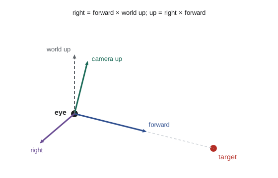
A virtual camera has a position (the eye), an orientation and a projection (lesson 5). The view matrix transforms world coordinates into camera coordinates, in which the eye is at the origin and, by OpenGL convention, the camera looks down the negative z axis with y up and x to the right. Because it re-expresses the world relative to the camera, the view matrix is the inverse of the camera's model matrix: if the camera were an object placed in the world by rotation \(R\) and translation \(e\), then \(V = R^{T}\) followed by translation \(-R^{T}e\).
The common way to aim a camera is lookAt, which builds the camera's axes from the eye position, a target point and an approximate up vector. The forward direction is \(f = (\text{target} - \text{eye})/\lVert\text{target} - \text{eye}\rVert\). The right direction is \(r = f \times \text{up}\), normalized, and the true up is \(u = r \times f\), which is perpendicular to both even if the supplied up vector was not. The rotation part of the view matrix has rows \(r\), \(u\) and \(-f\), and the translation part is \(-R\,\text{eye}\). LookAt fails if the up vector is parallel to the viewing direction, for example when looking straight down with up = (0, 1, 0), because the cross product vanishes; cameras that look straight up or down need a different reference vector.
# Building a view matrix with lookAt (right-handed, camera looks down -z),
# and checking that the target lands on the camera's viewing axis.
import numpy as np
np.set_printoptions(precision=3, suppress=True)
def look_at(eye, target, up):
    eye, target, up = (np.asarray(v, float) for v in (eye, target, up))
    f = target - eye; f /= np.linalg.norm(f)          # forward
    r = np.cross(f, up); r /= np.linalg.norm(r)       # right
    u = np.cross(r, f)                                # true up
    V = np.eye(4)
    V[0, :3], V[1, :3], V[2, :3] = r, u, -f           # rows: camera axes
    V[:3, 3] = -V[:3, :3] @ eye                       # then move eye to origin
    return V
eye, target = (6.0, 4.0, 8.0), (0.0, 1.0, 0.0)
V = look_at(eye, target, (0, 1, 0))
print("view matrix:\n", np.round(V, 3) + 0.0)
for name, p in (("eye", eye), ("target", target), ("point above target", (0, 3, 0))):
    print(f"{name:18} -> view space {np.round(V @ np.append(p, 1.0), 3) + 0.0}")
# Orbit camera: eye on a circle around the target, as an interactive viewer would
for deg in (0, 90, 180):
    a = np.radians(deg)
    e = (8 * np.sin(a), 4.0, 8 * np.cos(a))
print(f"orbit {deg:3} deg: target at depth {-(look_at(e, target, (0, 1, 0)) @ [0, 1, 0, 1])[2]:.3f}")view matrix: [[ 0.8 0. -0.6 0. ] [ -0.172 0.958 -0.23 -0.958] [ 0.575 0.287 0.766 -10.728] [ 0. 0. 0. 1. ]] eye -> view space [0. 0. 0. 1.] target -> view space [ 0. 0. -10.44 1. ] point above target -> view space [ 0. 1.916 -9.866 1. ] orbit 0 deg: target at depth 8.544 orbit 90 deg: target at depth 8.544 orbit 180 deg: target at depth 8.544
The eye maps to the origin of view space, and the target lands on the negative z axis at a depth equal to its distance from the eye, about 10.4 units, with zero x and y: it is centered in the view. A point above the target has positive y in view space, so it appears above the center. The orbit loop shows the target staying at the same depth as the camera circles it, which is what an interactive model viewer does.
Interactive camera controls come in a few standard styles. A first-person camera stores yaw and pitch angles, clamps pitch to just under 90 degrees to avoid the lookAt singularity and gimbal lock, and builds the view matrix each frame. An orbit (turntable) camera keeps a target and moves the eye on a sphere around it using azimuth, elevation and distance. An arcball, introduced by Shoemake in 1992, maps mouse drags onto a virtual sphere and turns them into quaternion rotations, giving intuitive free rotation of an object. Flight and space simulators store camera orientation as a quaternion and apply incremental rotations, renormalizing each frame, because they must handle every orientation without singularities.
Worked examples
Worked problem
A quaternion from axis and angle
Write the unit quaternion for a rotation of 60 degrees about the y axis, and rotate the vector (1, 0, 0).
Show solution
- Half angle 30 degrees: \(q = (\cos 30°, 0, \sin 30°, 0) = (0.866, 0, 0.5, 0)\).
- Rotating x about y by 60 degrees (right-hand rule) moves it toward \(-z\): \((\cos 60°, 0, -\sin 60°) = (0.5, 0, -0.866)\).
- Computing \(q(0,1,0,0)q^{*}\) gives the same result.
Answer: q = (0.866, 0, 0.5, 0), and (1, 0, 0) rotates to (0.5, 0, −0.866).
Worked problem
Slerp at the midpoint
Interpolate halfway between the identity and a 90-degree rotation about z.
Show solution
- \(q_0 = (1, 0, 0, 0)\), \(q_1 = (\cos 45°, 0, 0, \sin 45°) = (0.707, 0, 0, 0.707)\).
- \(\cos\Omega = 0.707\), so \(\Omega = 45°\); at \(t = 0.5\) both weights are \(\sin 22.5° / \sin 45° = 0.541\).
- Result: \(0.541(1, 0, 0, 0) + 0.541(0.707, 0, 0, 0.707) = (0.924, 0, 0, 0.383) = (\cos 22.5°, 0, 0, \sin 22.5°)\).
Answer: A 45-degree rotation about z, exactly halfway, as expected.
Worked problem
LookAt axes
A camera at (0, 5, 5) looks at the origin with world up (0, 1, 0). Find its forward, right and up vectors.
Show solution
- Forward: \((0, -5, -5)/\sqrt{50} = (0, -0.707, -0.707)\).
- Right: \(f \times \text{up} = (0, -0.707, -0.707) \times (0, 1, 0) = (0.707, 0, 0)\), normalized to (1, 0, 0).
- Up: \(r \times f = (1, 0, 0) \times (0, -0.707, -0.707) = (0, 0.707, -0.707)\).
Answer: Forward (0, −0.707, −0.707), right (1, 0, 0), up (0, 0.707, −0.707): the camera is tilted 45 degrees downward.
Common mistakes
MistakeInterpolate rotation matrices or Euler angles component by component.
InsteadConvert to quaternions and use slerp or nlerp.
MistakeForget that q and −q are the same rotation when interpolating.
InsteadNegate one quaternion if their dot product is negative so the shorter arc is taken.
MistakeLet a first-person camera pitch reach exactly 90 degrees.
InsteadClamp pitch slightly below 90 degrees to avoid the lookAt singularity and gimbal lock.
MistakeAccumulate incremental rotations in a matrix without correction.
InsteadStore orientation as a quaternion and renormalize, or re-orthonormalize the matrix periodically.
MistakeAssume every tool uses the same axes and Euler order.
InsteadCheck handedness, up axis and rotation order when exchanging data.
Summary and key terms
- Rotation matrices are orthogonal with determinant 1; they are fast to apply but redundant and cannot be averaged.
- Euler angles are compact but have many conventions and suffer gimbal lock when two axes align.
- Any rotation is a single rotation about an axis (Euler's theorem); Rodrigues' formula applies it to vectors.
- Unit quaternions \((\cos\frac{\theta}{2}, \hat{k}\sin\frac{\theta}{2})\) compose by multiplication and rotate vectors by \(qvq^{*}\).
- Slerp interpolates at constant angular speed along the great arc; nlerp is cheaper with slightly uneven speed.
- The view matrix is the inverse of the camera's placement and puts the eye at the origin looking down −z.
- LookAt builds the camera axes from eye, target and up, and fails when up is parallel to the view direction.
- Euler angles
- Three angles describing an orientation as successive rotations about coordinate axes.
- Gimbal lock
- Loss of one rotational degree of freedom when two Euler rotation axes align.
- Axis-angle
- A rotation described by a unit axis and an angle about it.
- Quaternion
- A four-component number w + xi + yj + zk; unit quaternions represent 3D rotations.
- Slerp
- Spherical linear interpolation along the great-circle arc between two unit quaternions.
- Nlerp
- Normalized linear interpolation of quaternions, renormalized after linear blending.
- Double cover
- The property that q and −q represent the same rotation.
- View matrix
- The matrix that transforms world coordinates into camera coordinates.
- LookAt
- A construction of the view matrix from an eye point, a target point and an up vector.
- Arcball
- A rotation controller that maps mouse drags onto a virtual sphere.
Practice problems
Work each problem on paper first, then reveal the answer to check.
How many degrees of freedom does a 3D rotation have, and how many numbers does a rotation matrix store?
Show answer
Three; nine.
When does gimbal lock occur for yaw-pitch-roll angles?
Show answer
When pitch is ±90 degrees, aligning the yaw and roll axes.
Write the quaternion for 180 degrees about the x axis.
Show answer
(0, 1, 0, 0).
How do you invert a unit quaternion?
Show answer
Take its conjugate, negating the vector part.
Why does slerp check the sign of the dot product?
Show answer
To take the shorter arc, since q and −q represent the same rotation.
When does nlerp agree exactly with slerp?
Show answer
At the endpoints and the midpoint.
Which way does an OpenGL-convention camera look in view space?
Show answer
Down the negative z axis.
Why does lookAt recompute up as r × f?
Show answer
To make the camera's up exactly perpendicular to forward and right.
What goes wrong if lookAt's up vector is parallel to the view direction?
Show answer
The cross product is zero, so the right vector is undefined.
What is Rodrigues' formula used for?
Show answer
Rotating a vector about a unit axis by a given angle.
Lesson quiz · 5 questions
Score 60% or more to complete this lesson.
Create a free account to save your progress, take quizzes and earn a certificate.