
BAS-120 · Lesson 9 of 12 · 23 min
Wiring field devices: 0-10 V, 4-20 mA and resistive inputs
▶ Video coming soon A video version of this lesson is on the way.
On Monday, November 9, Prakash and Callie were back in Ninefield Tower's basement plant room, chasing a reading that would not sit still. The differential pressure transmitter that controlled the secondary chilled water pumps, which BAS-110 had noted ran at about 52 Hz all day, had begun to jump. Every few seconds the reading leapt by 3 or 4 psi and fell back, and the pumps surged with it. Earlier in the year, the two penthouse economizer actuators had also started to sit a few degrees open when commanded closed. By the end of the day they had found that both problems were wiring, not devices, and Callie had learned more about cable, shields and commons than in any classroom.
This lesson explains how field devices are wired to controllers: voltage signals, current loops and resistive sensors, the cable and shielding each needs, the 24-volt power and common wiring that ties many devices together, and the separation rules between control and power wiring. BAS-210 covers the controller side of the panel; this lesson stays with the field wiring from the device back.
Wiring a voltage signal
A 0 to 10 V or 2 to 10 V device usually has three wires: 24 V power, common and signal. The device's signal is measured between the signal wire and the common, so the common does two jobs: it carries the device's power return current and it is the reference for the signal. If the common wire has resistance and carries current, a voltage drop appears along it, and the controller sees that drop added to or subtracted from the signal. On a single sensor drawing a few milliamps the effect is negligible, but when several actuators share a long common with a sensor's signal reference, the error can be large.
Worked problem
Error from a shared common
Four modulating damper actuators and a 0 to 10 V position feedback share one 18 AWG common wire 100 ft long back to the controller. While the actuators drive, their combined current in the common is about 1.2 A. Taking 18 AWG copper as 6.4 Ω per 1,000 ft, what voltage error appears on the feedback, and how large is that on a 0 to 10 V, 0 to 100 in 100 signal?
Show solution
- Common resistance: 100 × 6.4 ÷ 1,000 = 0.64 Ω.
- Voltage drop: 1.2 × 0.64 = 0.77 V.
- On a 10 V span: 0.77 ÷ 10 = about 7.7 in 100 of full scale.
Answer: An error of about 0.8 V, nearly 8 in 100 of the signal, which comes and goes as the actuators move. The fix is a separate signal common run back to the controller, or a heavier power common, as the manufacturer's wiring diagram shows.
That was the penthouse economizer problem. When the penthouse units were modified in 2019, an installer had used one common for the actuators' power and the controller's analog outputs to save a conductor. With the actuators holding still, the drop was small; at the moment the controller commanded the dampers closed, all the actuators drew driving current together, the common's voltage shifted, and each actuator saw a signal a few tenths of a volt above zero. A 2 to 10 V actuator ignores small offsets near zero, but these were 0 to 10 V actuators, and they settled a few degrees open. Callie traced the commons on the drawing and in the panel, and Prakash ran a separate signal common for each actuator from the controller's output terminals. The dampers closed fully.
Wiring a 4 to 20 mA loop
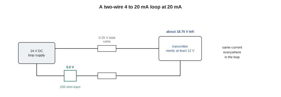
A current loop works differently. In a two-wire, loop-powered transmitter, a DC supply, the transmitter and the controller's input are all in series. The transmitter regulates the current flowing around the loop to between 4 and 20 mA according to its measurement, and the controller measures the current, usually as the voltage across a resistor of about 250 Ω, which turns 4 to 20 mA into 1 to 5 V. Because the same current flows everywhere in a series loop, wire resistance does not change the reading, provided the supply has enough voltage left over to drive the full 20 mA. That is why current loops are preferred for long runs and noisy places.
Some transmitters need their own power and use three or four wires: a separate supply pair and a current output. Controllers may also supply loop power themselves from a terminal, or expect an external supply. Getting the polarity and the power arrangement right is the first job when a new 4 to 20 mA device reads zero.
Worked problem
Checking a loop budget
Ninefield's chilled water differential pressure transmitter needs at least 12 V at its terminals. The loop supply is 24 V DC, the controller's input resistor is 250 Ω, and the transmitter is 1,000 ft of 18 AWG cable away (2,000 ft of conductor). Is there enough voltage at 20 mA? What is the most total loop resistance the supply could drive?
Show solution
- Input resistor drop at 20 mA: 0.020 × 250 = 5.0 V.
- Wire resistance: 2,000 × 6.4 ÷ 1,000 = 12.8 Ω; drop: 0.020 × 12.8 = 0.26 V.
- Voltage left for the transmitter: 24 − 5.0 − 0.26 = 18.74 V, more than the 12 V it needs.
- Most loop resistance: (24 − 12) ÷ 0.020 = 600 Ω.
Answer: There is plenty of margin: the loop could tolerate up to 600 Ω in total. Problems arise when extra devices, such as a local display or a second input, are added in series, or when the supply is lower than assumed.
Noise, shields and the jumping reading
The jumping pressure reading was not the loop budget. Callie found the transmitter cable tied to a cable tray beside the output cables of the secondary pump drives for about 50 ft. A variable frequency drive's output switches the motor voltage on and off thousands of times a second, and its cables radiate strong electrical noise. Cable carrying a small signal close and parallel to drive output cable picks up that noise. The transmitter's cable was a shielded twisted pair, which should have resisted it, but its shield was connected to ground at both ends: at the controller panel and at the transmitter's housing, which was bonded to the pipe.
A shield works by intercepting electrical noise and draining it to ground. If it is grounded at both ends, and the two grounds are at slightly different potentials, which is common in buildings with large motors and long runs, current flows along the shield itself. That ground loop current induces noise into the very conductors the shield is meant to protect. The general rule in building controls, unless the manufacturer says otherwise, is to ground a signal cable's shield at one end only, usually at the controller panel, and to fold back and insulate it at the device end. Twisting the pair helps as well, because noise induced in the two conductors is nearly equal and cancels.
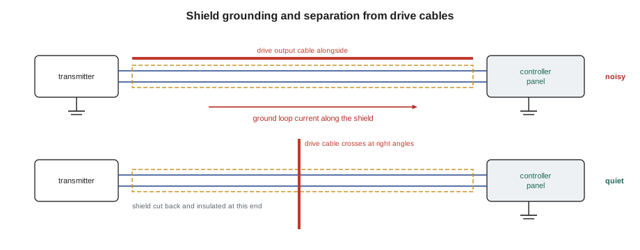
Prakash and Callie disconnected the shield at the transmitter, insulated it, and moved the cable off the drive tray onto its own supports a 12 in away, crossing the drive cables at right angles where it had to. The reading settled immediately. They trended it for an hour and saw it hold within a fraction of a psi of setpoint, with the pumps steady.
Resistive inputs
Thermistors and RTDs connect with two conductors to a controller input that supplies a small current and measures the resulting voltage. Lesson 2 showed that wire resistance is negligible for a thermistor but matters for an RTD on a long run. Resistive inputs are also sensitive to anything else in the circuit: a corroded splice, a loose terminal or moisture in a junction box adds resistance that a thermistor input reads as a colder temperature. Use proper connectors, keep splices in boxes, and do not share a sensor's conductors with any other circuit. Resistive sensor cable should be twisted pair and, in electrically noisy places, shielded with the shield grounded at one end.
24-volt power and commons
Most field devices run on 24 V AC from Class 2 transformers. Each transformer has two secondary terminals, often labeled 24 V (or hot) and common. Many controllers and devices bond the common side to ground internally, and many actuators use half-wave rectifiers that draw current from only one side of the transformer. If two devices powered from the same transformer are wired with their hot and common reversed, or if devices on different transformers have their commons tied together on opposite legs, current can flow through the device's electronics or the controller's ground, damaging them or causing erratic readings. The rule is to keep 24 V AC polarity consistent: hot to hot, common to common, with the transformer's common side grounded where the manufacturer requires, and not to tie commons between transformers unless the documents say to.
| Wiring type | Typical conductors | Cable | Key rules |
|---|---|---|---|
| 0 to 10 V or 2 to 10 V sensor or actuator | Power, common, signal (plus feedback) | 18 AWG multi-conductor, shielded where noisy | Separate signal common on long or shared runs |
| 4 to 20 mA two-wire transmitter | Loop positive and negative | Shielded twisted pair | Check polarity and loop budget; shield grounded at one end |
| Thermistor or RTD | Two conductors (three or four for some RTDs) | Twisted pair, shielded where noisy | No shared conductors; sound splices |
| Binary input (dry contact) | Two conductors | Twisted pair or multi-conductor | No outside voltage on a dry-contact input |
| 24 V AC power | Hot and common | 18 or 16 AWG | Keep polarity consistent; size transformers for the load |
Separating control and power wiring
Building controls wiring is mostly Class 2: low-voltage, power-limited circuits whose transformers are built so that the available current and power cannot cause a fire or a dangerous shock. The National Electrical Code sets rules for Class 2 wiring, including keeping it separate from power and lighting conductors, usually by a barrier or a separate raceway, unless both are insulated for the higher voltage or another permitted method is used. Running Class 2 cable loose in the same box or conduit as 120 V or 600 V conductors is not allowed. Plenum spaces need cable rated for use there. The rules also protect the controls themselves: separation keeps induced noise away from signals, as Ninefield's drive tray showed.
Line-voltage work requires a licensed electrician under Ohio and local rules, and controls contractors install Class 2 wiring under the code's rules, with permits and inspections as the local authority requires. A controls technician who opens a panel containing both kinds of wiring treats the whole panel as live line voltage until it is proven otherwise.
Labeling and termination practice
- Label every conductor at both ends with its point name or a number that appears on the drawings.
- Use ferrules on stranded wire in screw terminals, and torque terminals to the manufacturer's value.
- Leave a service loop at each device so it can be removed and replaced.
- Keep signal and power conductors on different sides of a panel where possible, and cross them at right angles where they must meet.
- Record on the as-built drawings where shields are grounded, where commons are shared and where power comes from.
Checking field wiring
When a field device misbehaves, the wiring is checked in a set order. First, look: a loose or burnt terminal, a pinched cable, water in a box or a splice wrapped in tape often explains everything. Second, measure with the circuit live: supply voltage at the device, signal voltage or loop current, and the voltage between the device's common and the controller's common, which should be close to zero. Third, with the circuit isolated, check continuity and insulation: each conductor end to end, and no unwanted continuity between conductors or to ground. A cable that tests fine with no voltage on it and fails in service is often picking up noise, which a trend or an oscilloscope can show.
Common mistakes
MistakeSharing one common between actuator power and analog signals on a long run.
InsteadRun a separate signal common, as the wiring diagram shows.
MistakeGrounding a shield at both ends.
InsteadGround it at one end, usually the controller, unless the manufacturer says otherwise.
MistakeRunning signal cable alongside drive output cables.
InsteadKeep it apart and cross at right angles.
MistakeAdding a local display into a 4 to 20 mA loop without checking the loop budget.
InsteadAdd up the resistances and check the transmitter still gets its minimum voltage at 20 mA.
MistakeReversing 24 V AC hot and common between devices.
InsteadKeep polarity consistent on every device and transformer.
MistakePutting Class 2 cable loose in a box with line-voltage conductors.
InsteadSeparate it by a barrier or raceway as the electrical code requires.
Summary and key terms
- Voltage signals are referenced to a common; current in a shared common adds an error to the signal.
- 4 to 20 mA loops are immune to wire resistance as long as the loop budget leaves the transmitter enough voltage.
- Loop budget: supply voltage minus the drops across the input resistor and wires must exceed the transmitter's minimum.
- Shielded twisted pair rejects noise; ground the shield at one end and keep signal cable away from drive outputs.
- Resistive inputs read any added resistance as part of the measurement; keep splices sound.
- Keep 24 V AC polarity consistent, and separate Class 2 wiring from power wiring as the electrical code requires.
- Common
- The return conductor and voltage reference shared by power and signals.
- Loop-powered transmitter
- A two-wire 4 to 20 mA transmitter that takes its operating power from the loop current.
- Loop budget
- The check that a current loop's supply voltage covers all the drops in the loop at 20 mA.
- Shielded twisted pair
- A pair of twisted conductors wrapped in a conducting shield.
- Ground loop
- Unwanted current flowing between two ground points at different potentials, often along a shield.
- Class 2 circuit
- A power-limited low-voltage circuit with its own wiring rules.
- Half-wave rectifier
- A circuit in a device that draws power from only one side of an AC supply.
- Ferrule
- A metal sleeve crimped onto stranded wire for a secure terminal connection.
Practice problems
Work each problem on paper first, then reveal the answer to check.
A loop has a 24 V supply, a 250 Ω input and a transmitter needing 10 V. What is the most total loop resistance at 20 mA?
Show answer
(24 − 10) ÷ 0.020 = 700 Ω, including the 250 Ω input.
Why does wire resistance not change a 4 to 20 mA reading?
Show answer
The same current flows everywhere in a series loop, and the controller measures the current.
Where should a signal cable's shield normally be grounded?
Show answer
At one end only, usually at the controller panel.
Several 0 to 10 V actuators sit slightly open when commanded closed after a retrofit. What wiring problem should be checked?
Show answer
A shared common carrying actuator current, which offsets the signal.
Why keep signal cable away from drive output cable?
Show answer
Drive outputs switch rapidly and induce noise into nearby signal conductors.
Lesson quiz · 5 questions
Score 60% or more to complete this lesson.
Create a free account to save your progress, take quizzes and earn a certificate.