
BAS-120 · Lesson 12 of 12 · 21 min
Field device installation and documentation
▶ Video coming soon A video version of this lesson is on the way.
On Monday, November 2, Callie installed her first field device from start to finish without Prakash beside her. AHU-1's mixed air averaging sensor had been reading erratically since the freezestat tests in October, and when she pulled it out she found the element kinked at a sharp bend and its outer sheath split. Prakash checked her plan in the morning and then left for Ninefield. "The sensor's the easy part," he said. "What makes it a good job is that the next person can find it, understand it and replace it without calling you." By the end of the day the new sensor was in, checked and documented, and the point list, the as-built drawing, the label in the panel and the tag on the device all said the same thing.
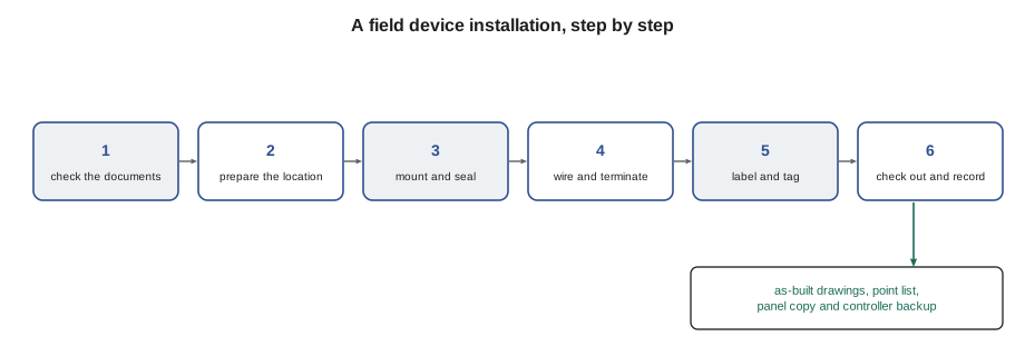
This lesson brings the course together. It covers the practical work of installing field devices well: planning, choosing locations, mounting, wiring and terminating, labeling and tagging, checking out each point, and keeping the documents that let a building be maintained for decades. Most problems this course has described, from the swapped tubes at Ninefield to the miswired freezestat on AHU-2, were installation and documentation failures, not device failures.
Before installing: the documents
Field devices are installed from a set of documents that the controls contractor produces and the engineer reviews. The controls drawings show the system schematic, the location of every device, the wiring diagrams and the panel layouts. The points list, or point schedule, lists every input and output with its name, type, range, units, device model, controller and terminal. The sequence of operation says what the system does with each point. The device data sheets and installation instructions say how each device must be mounted, wired and set. On a new project these go to the engineer as a submittal before installation; on a service replacement, the technician works from the existing as-built set and updates it.
Before Callie ordered the replacement averaging sensor, she checked four things in the documents: the sensor type and curve (10K Type II thermistor, as lesson 2 found for the rest of Tilden), the required element length for the plenum, the controller input it landed on, and the sequence's use of mixed air temperature, which was in the economizer logic and the freeze protection logic. That last check mattered: a mixed air sensor that read wrongly could open the outdoor air dampers too far on a cold morning.
Choosing and preparing the location
The design shows where each device goes, but the installer must make that location work. The guidance in earlier lessons applies: temperature sensors where they measure the air or water they are meant to measure, pressure probes in straight duct away from fittings, flow meters with their straight runs, CO2 sensors in the breathing zone, freezestats across the whole coil face. The installer also has to think about access. A sensor that can only be reached by removing a ceiling grid and a duct panel will not be checked. Mount devices where a technician can reach them with a ladder and a meter, with enough clearance to remove them, and away from where they can be stepped on, struck or soaked.
Averaging sensors need an element long enough to cover the duct or coil face in a serpentine pattern, with even coverage. Manufacturers publish a rule for each element, often expressed as a length per unit of face area. AHU-1's mixing plenum was the same size as its preheat coil face, 40 ft². The original sensor had a 24 ft element, about 0.6 ft of element per square foot of face, and that matched the manufacturer's guidance for the new one, so she ordered the same length.
Worked problem
Laying out an averaging element
The mixing plenum is 8 ft wide and 5 ft high. The 24 ft element is to be strung horizontally in passes across the width, with about 1 ft left over for the run to the enclosure. How many passes can it make, and how far apart will they be?
Show solution
- Element available for passes: 24 − 1 = 23 ft.
- Passes: 23 ÷ 8 = 2.9, so 3 full passes would need 24 ft; plan 3 passes with the last slightly short.
- Spacing: 5 ft ÷ 3 = about 20 in apart, with the first pass about 10 in from the bottom.
Answer: Three passes, about 20 in apart, covering the lower part of the plenum where cold outdoor air tends to stratify as well as the top. The element bends around supports at each end, never at a sharp corner.
The old element had been kinked where it was pulled tight around the edge of a damper frame instead of a proper support. Callie used the manufacturer's capillary clips on short lengths of rod at each end of the passes, kept the bends gentle, and left the element slightly slack so that vibration would not rub it.
Mounting and wiring
- Mount the device with the hardware the manufacturer supplies or specifies, on a surface that will not vibrate it loose.
- Seal every penetration: duct penetrations with gaskets or sealant so air does not leak, wall penetrations behind room sensors so wall-cavity air does not reach the element.
- Run cable in the specified way: plenum-rated where required, supported at intervals, protected where it can be damaged, separated from power wiring as lesson 9 described.
- Terminate with ferrules on stranded wire, to the correct terminals, torqued as specified, with shields handled as the drawings show.
- Leave a service loop at the device and a neat, labeled loop in the panel.
- Set the device's switches, jumpers or menu settings to match the point list: range, output type, units and any built-in features such as automatic calibration.
Labeling and tagging
Every field device should be identifiable on site and on paper by the same name. The point name in the controller and the front end, the label on the conductor at both ends, the tag on the device and the name on the drawing should match. Most projects follow a naming convention set by the owner or the engineer, built from the building, the system, the equipment and the point, for example something like TH.AHU1.MAT for Tilden Hall, AHU-1, mixed air temperature. Consistent names make alarms meaningful, let trends be found and let analytics software map points automatically. Some owners also use semantic tagging schemes, such as Project Haystack tags or the Brick schema, that describe each point's meaning in a machine-readable way.
Callie printed a tag for the new sensor's enclosure reading TH.AHU1.MAT with the sensor type, 10K TYPE II, and the controller and terminal; put matching wire labels on both conductors at the sensor and in the panel; and updated the label strip on the controller's terminal block. In the panel door's document pocket she wrote the change on the point list with the date.
| Item | Example for the new sensor |
|---|---|
| Point name | TH.AHU1.MAT |
| Description | AHU-1 mixed air temperature, averaging |
| Point type | Analog input |
| Device | 10K Type II thermistor averaging element, 24 ft |
| Controller and terminal | AHU-1 controller, input 4 |
| Range and units | −40 to 122 °F |
| Used in sequence | Economizer mixed air control; low mixed air alarm |
| Installed and checked | Mon Nov 2 2026, Callie Rintoul; reference reading recorded |
Point checkout
Every new or replaced point is checked out before it is handed over. Point-to-point checkout confirms, for each point, that the field device, the wiring, the controller input or output, the configuration and the front end display all agree. For an input, the technician compares the front end reading with a reference or a simulated signal, as lesson 10 described. For an output, the technician commands it through its range and watches the device respond. For a binary point, the technician operates the device or contact and watches the state change. Each result is recorded on a checkout sheet, which becomes part of the commissioning record on a new project.
Callie checked the new sensor three ways. She measured its resistance with one lead disconnected and compared it with the curve at the reference thermometer's reading in the plenum. She reconnected it and compared the front end reading with the reference. Then she watched the reading during the morning economizer cycle, as the outdoor air damper modulated: the mixed air temperature followed the damper smoothly, between the outdoor and return temperatures, as it should. The checkout sheet had all three results.
As-built documents and handover
As-built drawings show what was actually installed, not what was planned. Devices move during installation, cable routes change, a sensor goes in a different input because a terminal was damaged, a setting is changed to suit the site. Every such change goes on the drawings, the point list and the controller's database before the job is closed. On a new project, the controls contractor hands over the as-built drawings, the final point list, the sequences, the device data sheets, the checkout and commissioning records, the controller backups and the training material. On service work, the technician updates the existing set and the panel copy, and the company's records.
Buildings outlive the people who installed their controls by many years. The Ninefield building pressure tube that was cut in 2024, the Tilden actuator switched to the wrong range years before Callie arrived, the copied K-factor on a VAV box and the freezestat turned into a control by a time delay: in every case, someone made a change that was not recorded, and someone else spent hours finding it. Good documentation is what turns a set of devices into a system that can be maintained.
Callie's day, reviewed
When Prakash came back that afternoon, he read the checkout sheet first, then the panel label, then the tag on the sensor, then the front end. Everything matched. He pointed out one thing she had missed: the controller's database backup on the Quillon server was dated September, before her change and before the safety tests in October. She made a new backup and named it with the date. "Now if that controller dies tonight," he said, "we can put back exactly what's in there today." BAS-210 covers controller backups and databases in detail.
Working safely during installation
Field device work brings a controls technician into ceilings, mechanical rooms, roofs and occupied spaces. Ladders and lifts need the same care as on any job site: the right ladder for the height, three points of contact, and fall protection on roofs and open edges as OSHA's rules require. Mechanical rooms hold rotating equipment, hot pipes and line-voltage panels; a fan that the BAS can start remotely must be locked out before anyone reaches into its housing, even to mount a sensor, because a schedule or a remote operator can start it without warning. Working above ceilings in older buildings raises the possibility of asbestos-containing materials in pipe insulation, duct wrap or fireproofing; check the building's asbestos records before disturbing anything, and stop if you find suspect material.
In occupied buildings, the controls technician is also a visitor. Tell the building operators before taking equipment out of automatic control, put it back afterwards, and leave the space as clean as it was found. At Tilden, Callie had told Nell she would have AHU-1 in hand for an hour while she replaced the sensor, picked a time when the classrooms it served were empty, and called her again when the unit was back in automatic. Those small courtesies are part of why building operators trust a controls contractor with their systems.
The day's last job was the one most often skipped. Callie walked back to the plenum with the reference thermometer at the end of the afternoon, when the outdoor air damper had closed to minimum and the mixed air was close to return air temperature, and took a second comparison reading. The two readings, one in the morning with cold outdoor air mixing in and one in the afternoon near return temperature, checked the new element at two points of its working range, which was a better test than one reading alone. Both were within 0.4 °F of the reference, and she added the second reading to the checkout sheet before closing the work order.
Common mistakes
MistakeInstalling a device where nobody can reach it later.
InsteadMount devices where a technician can reach, test and replace them.
MistakePulling an averaging element tight around sharp edges.
InsteadUse supports and gentle bends, with slight slack.
MistakeLeaving duct or wall penetrations unsealed.
InsteadSeal them so leakage air does not affect the reading or the system.
MistakeUsing different names for the same point in the panel, the drawings and the front end.
InsteadUse one name, built from the naming convention, everywhere.
MistakeChanging a device's setting without recording it.
InsteadUpdate the point list, drawings, panel copy and database.
MistakeHanding over without a current controller backup.
InsteadBack up the controller after every change and date the file.
Summary and key terms
- Installation starts with the drawings, point list, sequence and device instructions.
- Choose locations that measure the right thing and can be reached for testing and replacement.
- Mount securely, seal penetrations, run and separate cable correctly and terminate neatly.
- Use one consistent point name on the device tag, conductor labels, panel, drawings and front end.
- Check out every point and record the results.
- Keep as-built documents and controller backups up to date; unrecorded changes cause most future faults.
- Points list
- The schedule of every input and output with its name, type, range, device and terminal.
- Submittal
- Documents sent to the engineer for review before installation.
- Naming convention
- An agreed pattern for building point names from building, system, equipment and point.
- Semantic tagging
- Machine-readable tags that describe what each point means.
- Point-to-point checkout
- Testing each point from the field device to the front end display.
- As-built drawings
- Drawings updated to show what was actually installed.
- Service loop
- Extra cable left at a device or panel so that it can be removed or replaced.
- Controller backup
- A saved copy of a controller's program and configuration.
Practice problems
Work each problem on paper first, then reveal the answer to check.
An averaging element is 20 ft long and must cross a 6 ft wide plenum with 1 ft left for the run to the enclosure. How many full passes can it make?
Show answer
(20 − 1) ÷ 6 = 3.2, so 3 full passes.
What should match across the device tag, wire labels, panel, drawings and front end?
Show answer
The point name.
What does point-to-point checkout confirm?
Show answer
That the device, wiring, controller configuration and front end display all agree.
Why are as-built drawings important?
Show answer
They show what was actually installed, so later technicians can find and fix things.
What should be done to a controller's backup after a change?
Show answer
Make a new backup and date it.
Lesson quiz · 5 questions
Score 60% or more to complete this lesson.
Create a free account to save your progress, take quizzes and earn a certificate.