
BAS-120 · Lesson 3 of 12 · 21 min
Humidity, pressure and differential pressure sensors
▶ Video coming soon A video version of this lesson is on the way.
On Wednesday, September 23, Prakash and Callie spent the day at Ninefield Tower with a list from Ilona Vescovi. The lobby doors whistled and were hard to open on windy afternoons; one of the penthouse air handlers showed a filter alarm that never cleared, even after the filters were changed in August; and a tenant on the seventh floor complained that the air felt dry, although the front end showed the humidity at a comfortable level. All three complaints came down to pressure and humidity sensors, and to the difference between what a sensor measures and what the building needs.
This lesson covers the sensors that measure humidity and pressure in buildings. Humidity sensors report how much moisture the air holds. Pressure sensors report the pressure in a duct or pipe relative to something else, and differential pressure sensors report the difference between two points, which is what most building measurements really are. The lesson explains how each works, what ranges and units are used, where they are mounted, and the mistakes that make their readings misleading.
Relative humidity and how it is sensed
Relative humidity (RH) is the amount of water vapor in the air compared with the most the air could hold at the same temperature, written in this course as a number in 100. Air at 72 °F and 40 in 100 RH holds 40 in 100 of the water vapor it could hold before condensation would start. Because warm air can hold much more water than cool air, the same moisture content gives a lower RH in warm air and a higher RH in cool air. That is why a humidity reading only means something when it is paired with a temperature, and why many humidity sensors also contain a temperature sensor.
Most building humidity sensors are capacitive. A thin polymer film between two electrodes absorbs water vapor from the air; as it does, its dielectric constant changes and so does the capacitance of the element. Electronics in the sensor convert the capacitance into a 0 to 10 V or 4 to 20 mA signal across a range of 0 to 100 RH. Good commercial sensors are accurate to about 2 or 3 in 100 RH when new. They drift over time, especially in dirty air, near chemicals or when exposed to condensation, and most manufacturers recommend checking them every year or two. A sensor that has been wet may read high for days, or permanently.
Other moisture measurements appear on drawings and in sequences. Dew point is the temperature at which the air would become saturated, and it does not change as the air warms or cools without moisture being added or removed. Many dehumidification sequences control dew point rather than RH for that reason, calculating it in the controller from an RH and a temperature measured together. Humidity ratio or absolute humidity is the mass of water per mass of dry air, used in psychrometric calculations and in some economizer logic.
The seventh-floor complaint
The front end showed 38 in 100 RH on the seventh floor, from a combination temperature and humidity sensor in the return duct. Callie took a calibrated handheld meter to the tenant's area and measured 24 in 100 RH at 73 °F. In the return duct beside the sensor, the meter agreed with the BAS. The difference was real, not a sensor fault: the return duct sensor sat downstream of a duct where air from the floor's kitchenette exhaust transfer had been tied into the return, bringing in moister air from the coffee machines and dishwasher. The sensor was accurate; it was just measuring the wrong air. Prakash added a note recommending a sensor in the occupied space for the humidity reading and left the return sensor for the economizer logic, which used the return enthalpy.
Dry air in winter is normal in cold-climate buildings without humidification, and the seventh floor at Ninefield had none. The point of the visit was to make sure the reading the building operators trusted reflected the space, so that their decisions about humidification would be made on good information. Ilona asked Declan for a price on an in-space sensor, which was added to the spring retro-commissioning list.
Pressure, gauge pressure and differential pressure
Pressure is force per unit area. Building automation measures three kinds. Absolute pressure is measured against a perfect vacuum; it is used for barometric pressure and some refrigeration measurements but rarely elsewhere in HVAC. Gauge pressure is measured against the surrounding atmosphere, which is what an ordinary pressure gauge on a water pipe shows. Differential pressure is measured between two points, such as the inside and outside of a duct, the two sides of a filter or the supply and return pipes of a water loop.
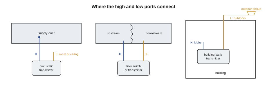
Almost every pressure measurement in an air system is a small differential pressure. Duct static pressure is the pressure inside a duct compared with the space around it. Building static pressure is the pressure inside the building compared with outdoors. Filter differential pressure is the drop across a filter bank. These pressures are tiny compared with atmospheric pressure, so they are measured in pascals in Canada and in inches of water column in the United States: 1 in. w.c. is about 249 Pa. A duct static setpoint of 1.5 in. w.c. is typical of a medium-pressure VAV system, a building pressure of 0.02 in. w.c. positive is a common target, and a clean filter bank may drop 0.3 in. w.c..
| Measurement | Typical range of the sensor | Typical reading | Low side tube goes to |
|---|---|---|---|
| Duct static pressure | 0 to 2 in. w.c. or 0 to 5 in. w.c. | 1.0 to 1.5 in. w.c. | The space or ceiling plenum near the duct |
| Building static pressure | ±0.1 in. w.c. | +0.01 to +0.05 in. w.c. | An outdoor pressure pickup |
| Filter differential pressure | 0 to 2 in. w.c. | 0.3 to 1.0 in. w.c. | The downstream side of the filter |
| Water differential pressure | 0 to 50 psi | 5 to 15 psi | The return pipe |
How pressure transmitters work
Most building pressure transmitters use a thin diaphragm with a high-pressure port on one side and a low-pressure port on the other. The difference in pressure flexes the diaphragm slightly, and a capacitive or strain-gauge element turns the movement into an electrical signal. Low-pressure air transmitters usually have selectable ranges and outputs set by switches or jumpers, and a zero button to correct for drift. Water pressure transmitters are built for much higher pressures, have threaded process connections, and are installed with isolation valves so that they can be removed or zeroed without draining the system.
Pressure switches are simpler devices that close or open a contact at an adjustable setpoint instead of sending an analog signal. They are used for filter alarms, fan airflow proving and high-pressure safeties. Lesson 11 covers the high static safety switch, which must work even if the controller fails.
The lobby doors
The whistling lobby doors pointed at building pressure. Ninefield's building static transmitter showed a steady +0.02 in. w.c., right at setpoint, while the doors were being pushed open by air rushing out. Callie followed the tubing from the transmitter's low port up the riser to the roof, where the outdoor reference pickup was supposed to be. She found the tube cut and taped off in the penthouse during a roofing repair in 2024, so the low port was reading the penthouse air instead of outdoors. The penthouse, full of air handlers, ran at a different pressure from the lobby, and the transmitter was faithfully reporting the difference between the two. The relief damper control used that reading, so it had been holding the wrong pressure for two years.
Worked problem
How far off was the building pressure?
After a temporary tube was run to an outdoor pickup, the true lobby pressure read +0.11 in. w.c. The setpoint is +0.02 in. w.c. How many times the setpoint is that, and what is it in pascals?
Show solution
- 0.11 ÷ 0.02 = 5.5 times the setpoint.
- 0.11 × 249 = about 27 Pa.
Answer: The building was running at about 0.11 in. w.c. positive, more than five times its design pressure, which explains doors that whistle and are hard to open.
Pressure of that size pushes conditioned air out through every crack, wastes energy and makes doors hard to use. With the tube repaired and a proper shielded outdoor pickup mounted on the roof, the relief damper opened further, and the lobby pressure settled near setpoint the next afternoon. Outdoor pickups for building pressure need shields that cancel the effect of wind blowing across the tube end, and they should be away from exhaust fans and roof edges. Many designs average several outdoor pickups on different faces of the building.
The filter alarm that never cleared
The penthouse air handler's filter switch was a pressure switch set to close at 1.0 in. w.c.. The filters had been replaced in August, yet the alarm stayed on. Callie read the actual drop across the new filters with a manometer: 0.36 in. w.c., well below the setpoint. The switch's high and low tubes had been swapped when the filter rack was rebuilt, so the switch was seeing a negative difference. That should have kept the contact open, but the switch's contact had also been wired to the normally closed terminal instead of the normally open one. Two mistakes together produced a permanent alarm. Callie swapped the tubes back and moved the wire to the correct terminal, then tested the switch by briefly covering part of the filter face with cardboard, which raised the drop past the setpoint and brought the alarm in. When she removed the cardboard, the alarm cleared.
Filter monitoring is more useful as an analog differential pressure reading than as a switch, because a trend shows how fast the filters are loading and lets maintenance plan changes before an alarm. Many new air handlers have analog filter transmitters for that reason. A sensible alarm point is usually set by the filter manufacturer's recommended final pressure drop, not a guess.
Water differential pressure and its location
Variable-speed pumps in chilled and hot water systems are usually controlled to hold a differential pressure between the supply and return pipes. Where that sensor is mounted matters as much as its accuracy. Mounted near the pump, it controls pressure where it is highest and wastes pump energy at low loads. Mounted near the most remote coil, often two-thirds of the way down the loop or at the end of the longest branch, it lets the pump slow down as long as the remote coils have enough pressure. BAS-110 noted that Ninefield's secondary pumps ran at about 52 Hz all day; part of the reason was that the differential pressure sensor was in the plant room beside the pumps. Moving it was another item for the retro-commissioning list.
Installing pressure and humidity sensors
- Use the right range: a sensor whose full scale is many times the reading has poor resolution and accuracy at the low end.
- Mount duct static probes in a straight section of duct, about two-thirds of the way down the main trunk unless the design says otherwise, and away from elbows and fittings that cause turbulence.
- Keep tubing short, supported, free of kinks and sloped so that moisture drains away from the transmitter. Label both ends: high and low.
- Mount water transmitters with isolation valves and an equalizing valve so that they can be zeroed and removed safely.
- Mount humidity sensors where the air represents the space, away from humidifier discharge where droplets can wet the element, and away from kitchens, showers and exterior doors.
- Zero low-pressure air transmitters after installation with both ports open to the same air, and record the date.
Units and conversions to keep handy
Pressure readings come in several units, and drawings, data sheets and front ends do not always agree. In the United States, air pressures are normally in inches of water column and water pressures in pounds per square inch or feet of head, but metric data sheets in pascals and kilopascals are common for imported equipment. The useful conversions are 1 in. w.c. ≈ 249 Pa, 1 psi ≈ 6.89 kPa, and 1 ft of water ≈ 2.99 kPa, or about 0.433 psi. When a transmitter's range is set in one unit and the controller's engineering units in another, the reading can be wrong by a large factor while looking perfectly plausible, so check both whenever a sensor is replaced.
Common mistakes
MistakeSwapping the high and low pressure tubes.
InsteadLabel both ends and check that a known pressure gives the expected sign.
MistakeTrusting a building pressure reading without checking the outdoor reference.
InsteadTrace the low-side tubing to a shielded outdoor pickup.
MistakeChoosing a pressure transmitter with a huge range for a small reading.
InsteadPick a range a little above the expected reading.
MistakePutting the pump differential pressure sensor beside the pump.
InsteadMount it near the remote end of the loop, as the design shows.
MistakeTreating a return duct humidity reading as the space humidity.
InsteadCheck what air the sensor actually sees.
MistakeLeaving a humidity sensor that has been soaked in service unchecked.
InsteadCheck it against a reference; replace it if it has drifted.
Summary and key terms
- Relative humidity is moisture compared with what the air could hold at that temperature; most sensors are capacitive and drift over time.
- Dew point is a better control variable than RH where moisture is the concern.
- Building air pressures are small differential pressures, measured in inches of water column; 1 in. w.c. is about 249 Pa.
- Duct static, building static and filter pressures each need the low port tubed to the right reference.
- Building pressure needs a shielded outdoor reference pickup.
- Pump differential pressure sensors belong near the remote end of the loop.
- Choose ranges that suit the reading, label tubing and zero transmitters after installation.
- Relative humidity (RH)
- Water vapor in the air compared with the maximum the air could hold at that temperature.
- Dew point
- The temperature at which air would become saturated with its present moisture.
- Gauge pressure
- Pressure measured relative to the surrounding atmosphere.
- Differential pressure
- The difference in pressure between two points.
- Duct static pressure
- The pressure inside a duct relative to the space around it.
- Building static pressure
- The pressure inside a building relative to outdoors.
- Pressure switch
- A device that opens or closes a contact at an adjustable pressure.
- Outdoor pressure pickup
- A shielded fitting that gives a building pressure sensor an outdoor reference unaffected by wind.
Practice problems
Work each problem on paper first, then reveal the answer to check.
Convert 250 Pa to inches of water column.
Show answer
About 1.0 in. w.c.
Why do dehumidification sequences often control dew point rather than RH?
Show answer
Dew point stays the same as air warms or cools without moisture change; RH does not.
A filter switch alarms with new filters. Name two wiring or tubing mistakes to check.
Show answer
Swapped high and low tubes, and the contact wired to the wrong terminal.
Where does the low port of a building pressure transmitter go?
Show answer
To a shielded outdoor pressure pickup.
Why mount a pump differential pressure sensor near the remote end of the loop?
Show answer
So the pump can slow down while still giving the remote coils enough pressure.
Lesson quiz · 5 questions
Score 60% or more to complete this lesson.
Create a free account to save your progress, take quizzes and earn a certificate.