
BAS-120 · Lesson 6 of 12 · 23 min
Damper actuators and linkages
▶ Video coming soon A video version of this lesson is on the way.
On Wednesday, October 14, Prakash took Callie to Ninefield Tower's podium roof to measure up the replacement actuators for the rooftop units. BAS-110 had described what they found there in September: on RTU-2 the outdoor air damper actuator had failed with the damper stuck about 20 in 100 open, and on RTU-3 the actuator's shaft coupling had slipped, so the actuator reported full travel while the damper barely moved. Ilona had approved the repairs, booked for early December. Before ordering parts, Prakash wanted Callie to size the new actuators properly instead of copying the old model numbers. "The last person copied the model number," he said, "and that's why it failed."
An actuator is the device that turns a controller's command into movement. This lesson covers damper actuators: how they work, the difference between spring return and non-spring return, floating and modulating control, how to size an actuator by torque, how actuators connect to dampers through direct couplings and linkages, and how to set up and check one. Lesson 7 covers valve actuators and valves.
Dampers and what they need from an actuator
A damper is a set of blades in a frame that controls airflow in a duct. Parallel-blade dampers have blades that all rotate the same way; they are used mostly for two-position duties and for mixing, where their airflow is less proportional to position. Opposed-blade dampers have adjacent blades rotating in opposite directions; they give a more gradual, controllable change in airflow and are preferred for modulating control. Dampers may have blade and jamb seals to reduce leakage when closed, which is important for outdoor air dampers in cold climates and for smoke and isolation dampers. Seals also make the damper harder to turn.
A damper needs torque to turn its blades against friction in its bearings and seals and against the force of the air on the blades. The torque rises with the damper's area, with seals, and with air velocity and pressure. A damper actuator must supply enough torque to open and close the damper reliably, with margin for dirt, corrosion and years of wear. An undersized actuator may work when new and then stall on a cold, windy morning, which is a common reason outdoor air dampers fail.
Types of damper actuator
Modern damper actuators are almost all electric: a small motor drives a gear train that turns an output shaft or coupling through 90 to 95 degrees. Most run on 24 volts AC or DC; some run on line voltage. Older buildings still have pneumatic actuators, where compressed air pushes a diaphragm and spring; BAS-130 covers those as legacy controls.
- Non-spring-return actuators stay where they are when power is lost. They suit dampers whose position on power failure does not matter, such as VAV box dampers and most zone dampers.
- Spring-return actuators wind up a spring as they drive open and return to a set position when power is removed or a safety opens their circuit. They are used where a damper must go to a safe position on power failure: outdoor air dampers that close to protect coils from freezing, and smoke and fire-smoke dampers that close on alarm.
- Electronic fail-safe actuators use a capacitor or battery instead of a spring to drive to a safe position on power loss.
Actuators are also described by how they are controlled. A two-position, or on-off, actuator drives fully open or fully closed on a binary output. A floating, or tri-state, actuator has two control wires, one to drive open and one to drive closed; with neither energized it stays put, and the controller positions it by timing how long it drives in each direction. A modulating, or proportional, actuator positions itself to match an analog signal, usually 0 to 10 V or 2 to 10 V, and often sends back a feedback signal of its actual position. Many modern actuators also accept a network connection that carries command, feedback and diagnostics.
| Control type | Wiring | How it is positioned | Typical use |
|---|---|---|---|
| Two-position | Power and one switched leg | Fully open or closed | Isolation dampers, exhaust fan dampers |
| Floating (tri-state) | Common, drive open, drive closed | By timed pulses; stays put with no signal | VAV boxes and terminal units |
| Modulating | Power, common, 0 to 10 V or 2 to 10 V signal, optional feedback | Matches the analog signal | Air handler mixing dampers, economizers |
| Network | Power and a communication bus | Commanded over the network, with feedback and diagnostics | New installations |
Floating actuators have a weakness: the controller only knows the position by counting drive time, so the estimate drifts. Good controllers drive the actuator fully closed periodically, or whenever the command reaches zero, to resynchronize. A VAV damper that has drifted can sit slightly open while the controller believes it closed, which matters when a room is overcooled at night.
Sizing an actuator by torque
Actuator manufacturers publish torque loading factors for different damper types: the torque needed per unit of damper area. The values below are typical published figures for dampers in ordinary duct conditions; the damper manufacturer's own torque figure, where it exists, takes precedence. For higher velocities or pressures, the loading is multiplied by a factor, and the selected actuator should have a rated torque at least equal to the result, normally the next size up.
| Damper type | Typical loading |
|---|---|
| Opposed blade, no seals | 3 in·lb per ft² |
| Parallel blade, no seals | 4 in·lb per ft² |
| Opposed blade, with seals | 5 in·lb per ft² |
| Parallel blade, with seals | 7 in·lb per ft² |
Worked problem
Sizing the RTU-2 outdoor air damper actuator
RTU-2's outdoor air damper is parallel-blade with seals, 48 in wide by 24 in high, in normal duct conditions. What torque does it need, and which standard size should be chosen if actuators come in 45, 90, 133 and 180 in·lb?
Show solution
- Area: 48 × 24 ÷ 144 = 8 ft².
- Loading for parallel blade with seals: 7 in·lb per ft².
- Torque needed: 8 × 7 = 56 in·lb.
- The 45 in·lb actuator is too small; choose 90 in·lb.
Answer: A 90 in·lb spring-return actuator. The failed actuator Callie removed was rated 45 in·lb, smaller than the damper needed.
That explained RTU-2. The original actuator had been about right for the damper when it was new and had no seals; when seals were added in a 2015 repair to stop cold air leaking in, nobody increased the actuator size. The smaller actuator had struggled for years and finally stalled. Prakash ordered 90 in·lb spring-return modulating actuators for both units, matching the failed actuator's signal type, 2 to 10 V with feedback.
Couplings and linkages
A direct-coupled actuator mounts straight onto the damper's drive shaft and clamps to it with a universal clamp, a V-bolt or a jackshaft coupling. Direct coupling is simple, accurate and needs no adjustment of linkage arms, and it is now the normal choice. The clamp must be the right size for the shaft and tightened to the manufacturer's torque; on round shafts, many clamps rely on friction, and a shaft that is too smooth or too small can slip, which is exactly what happened on RTU-3. Four weeks later, in BAS-110's room 108 case, Callie would see the same failure on a valve: an actuator turning freely while the device it was supposed to move stayed put.
A linkage connects an actuator to a damper through crank arms and a push rod, used where the actuator cannot sit on the damper shaft, where one actuator drives several damper sections, or where a stroke must be adjusted. Linkages need setting up: the crank arm lengths and angles determine how much damper rotation each degree of actuator travel produces, and a linkage set up badly can give a damper that is fully open when the actuator is only halfway, or never quite closes. Linkage ball joints wear and loosen, and set screws back out. Large dampers with several sections are often better served by one actuator per section, or by jackshafts that tie the sections together with the actuator mounted on the jackshaft.
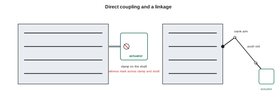
Prakash showed Callie a habit that makes slipping easy to see. After tightening a direct coupling, draw a line with a paint pen across the clamp and onto the shaft. If the line is later broken, the clamp has slipped. On RTU-3 there was no line, but scuffs on the shaft showed where the clamp had turned.
Setting up and checking a damper actuator
- Check the damper first: with the actuator disconnected, the blades should turn freely through their full range by hand or with a wrench on the shaft. A damper that binds needs repair, not a bigger actuator.
- Set the damper to its fail-safe position, usually closed for outdoor air, and mount the actuator with its spring return in the matching position.
- Set the actuator's direction of rotation and its signal range switches to match the controller's configuration.
- Tighten the coupling to the manufacturer's torque and add a witness mark.
- Stroke the actuator from 0 to 100 in 100 of command and watch the damper follow; check that feedback, if wired, matches the command.
- Remove power and check that a spring-return actuator returns the damper to its safe position.
- Many actuators can be adjusted to limit their travel or run an automatic adaptation of the stroke. Record any limits or settings.
On RTU-3, Callie and Prakash could not replace the actuator until December, but they could stop the immediate problem. They released the clamp, closed the damper by hand, tightened the clamp properly on the shaft with a witness mark and stroked it. The damper now followed the command. The replacement was kept on the order because the old actuator's clamp was worn and could slip again.
Powering actuators: transformer sizing
Most damper and valve actuators run on 24 volts AC from a Class 2 transformer in the control panel or the unit. Each actuator's data sheet gives its power draw in volt-amperes (VA) for sizing the transformer. Spring-return actuators draw more while they are driving and winding the spring than when they are holding, and the transformer must be sized for the moment when every actuator on it drives at once, such as when a unit starts up after a power failure. Actuators that share a transformer should also share a common wire correctly polarized, because a 24 V AC common tied to the wrong side of a transformer can damage controllers and actuators. Lesson 9 returns to the common wire.
Worked problem
Sizing a transformer for an air handler's actuators
An air handler has two spring-return damper actuators drawing 10 VA each while driving, and two valve actuators drawing 7 VA each. The controller draws 15 VA. Class 2 transformers come in 40, 75 and 100 VA sizes. Which should be used, allowing a margin of about 25 in 100?
Show solution
- Total load: 2 × 10 + 2 × 7 + 15 = 49 VA.
- With margin: 49 × 1.25 = about 61 VA.
- The 40 VA transformer is too small; choose 75 VA.
Answer: A 75 VA transformer. Class 2 transformers are limited to 100 VA each by code, so larger loads are split across several transformers, each on its own circuit.
An undersized transformer gives trouble that looks like other faults: actuators that stall or chatter on start-up, controllers that reset when several devices move at once, and readings that jump. A meter on the transformer's secondary during start-up shows whether the voltage sags well below 24 V.
Fire, smoke and combination dampers
Some dampers have a life-safety job. Fire dampers close automatically, usually by a fusible link melting, to keep fire from passing through a rated wall or floor in the ductwork. Smoke dampers close, or sometimes open, on a signal from the fire alarm system to control the movement of smoke. Combination fire and smoke dampers do both. Their actuators are part of a listed assembly, tested and listed with the damper, and they must not be replaced with an ordinary HVAC actuator. They are inspected and tested on a schedule set by the fire code and the standards it references. A controls technician may wire the BAS to read their end switches or to command them in a smoke control sequence, but the fire alarm and life-safety side of that work belongs to the fire alarm contractor and the building's life-safety program, as lesson 11 explains.
Common mistakes
MistakeCopying the old actuator's model number when replacing it.
InsteadSize the actuator from the damper's area, type, seals and conditions.
MistakeFitting a bigger actuator to a damper that binds.
InsteadFree the damper first; a binding damper will defeat any actuator in time.
MistakeUsing a non-spring-return actuator on an outdoor air damper in a cold climate.
InsteadUse spring return or electronic fail-safe so it closes on power loss.
MistakeTightening a direct coupling by feel.
InsteadUse the manufacturer's torque and add a witness mark.
MistakeLeaving a floating actuator without resynchronization.
InsteadDrive it fully closed periodically so the controller knows its position.
MistakeAssuming feedback proves the damper moved.
InsteadFeedback shows the actuator's position; look at the blades or the shaft.
Summary and key terms
- Opposed-blade dampers suit modulating control; parallel-blade dampers suit two-position and mixing duties; seals add torque.
- Spring-return and electronic fail-safe actuators drive to a safe position on power loss; non-spring-return actuators stay put.
- Actuators are two-position, floating, modulating or networked.
- Size an actuator by torque: area times a loading factor for the damper type, multiplied up for high velocity or pressure, then the next size up.
- Direct coupling is simple but must be tightened properly; linkages need careful setup and wear over time.
- Check the damper moves freely, set fail-safe position and signal range, stroke it, and test the spring return.
- Actuator
- A device that turns a controller command into movement of a damper or valve.
- Opposed-blade damper
- A damper whose adjacent blades rotate in opposite directions, giving more controllable airflow.
- Spring return
- An actuator feature that drives the device to a safe position on loss of power.
- Floating control
- Positioning an actuator by timed drive-open and drive-closed signals.
- Modulating actuator
- An actuator that positions itself to match an analog signal.
- Torque loading
- The torque a damper needs per unit of area.
- Direct coupling
- Mounting an actuator straight onto the damper shaft.
- Linkage
- Crank arms and push rods connecting an actuator to a damper.
Practice problems
Work each problem on paper first, then reveal the answer to check.
A 6 ft² opposed-blade damper with seals needs about how much torque?
Show answer
6 × 5 = 30 in·lb, so a 45 in·lb actuator.
Why do outdoor air dampers in cold climates usually have spring-return actuators?
Show answer
So they close on power loss and protect coils from freezing air.
What does a broken witness mark across a coupling and shaft show?
Show answer
That the clamp has slipped on the shaft.
Why do floating actuators need resynchronization?
Show answer
The controller estimates their position by drive time, which drifts.
What should you check before fitting a bigger actuator to a damper that stalls?
Show answer
Whether the damper binds; free it first.
Lesson quiz · 5 questions
Score 60% or more to complete this lesson.
Create a free account to save your progress, take quizzes and earn a certificate.