
BAS-120 · Lesson 4 of 12 · 23 min
Flow measurement for air and water
▶ Video coming soon A video version of this lesson is on the way.
On Wednesday, September 30, Callie and Prakash spent the morning on the second floor of Tilden Hall with a balancing report from 1999, a laptop connected to the VAV controllers and a flow hood borrowed from a balancing contractor. Gus had asked Quillon to check the airflow readings on a dozen VAV boxes before the heating season, because several rooms had been cold the previous winter and nobody could say whether the boxes were delivering what the front end claimed. In the afternoon they went to Ninefield to look at the chilled water flow meter that fed the plant's energy reports. By the end of the day Callie had seen most of the ways a building measures flow, and several of the ways those measurements go wrong.
Air and water flow are among the most important and least trusted measurements in a building. This lesson explains how airflow is measured with velocity pressure, pitot arrays and thermal dispersion sensors, how VAV boxes calculate their airflow from a flow pickup and a K-factor, and how water flow is measured with differential pressure devices, magnetic meters, ultrasonic meters and vortex meters. It finishes with the installation rules that decide whether any of them reads correctly.
Velocity pressure
Moving air has three pressures. Static pressure pushes outward on the duct walls in every direction. Velocity pressure is the extra pressure the air exerts in the direction it is moving because of its speed. Total pressure is the sum of the two. A pitot tube measures total pressure through a hole facing into the airstream and static pressure through holes on its side; the difference between them is the velocity pressure. Because velocity pressure rises with the square of velocity, velocity is proportional to the square root of velocity pressure.
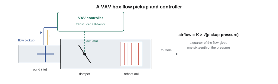
Airflow is velocity multiplied by the duct's cross-sectional area. The square-root relationship has an important consequence: velocity pressure is very small at low airflow. A VAV box running at a quarter of its maximum airflow produces only one sixteenth of its maximum velocity pressure, often just a pascal or two. Measuring such small pressures accurately is the hardest part of VAV control, and it is why many codes and sequences set minimum airflows that the box can actually measure.
Flow pickups and K-factors in VAV boxes
A VAV box's inlet usually has a flow pickup, a cross or ring of tubes with holes facing upstream and downstream. The difference between the two sides is an amplified version of the velocity pressure: the pickup's shape exaggerates the signal by a factor that depends on the design, often between about 1.5 and 3. Rather than work out velocity and area separately, the box manufacturer publishes a flow coefficient, usually called the K-factor, for each inlet size. The controller multiplies the square root of the measured pressure by the K-factor to get airflow directly.
Worked problem
Finding a VAV box K-factor
VAV-2-11 has an 8 in round inlet and a flow pickup that amplifies velocity pressure by 2.3. At its design maximum of 320 cfm, what velocity, velocity pressure and pickup signal does it see, and what is its K-factor?
Show solution
- Inlet area: π × (4 ÷ 12)² = 0.349 ft².
- Velocity: 320 ÷ 0.349 = 917 fpm.
- Velocity pressure: (917 ÷ 4005)² = 0.0524 in. w.c.
- Pickup signal: 0.0524 × 2.3 = 0.121 in. w.c.
- K = 320 ÷ √0.121 = 320 ÷ 0.347 = about 922 cfm per √in. w.c.
Answer: A K-factor of about 922. In practice the technician uses the manufacturer's published K-factor for the box size, then corrects it with a field measurement as described below.
The same relationship shows why low flows are hard. At a minimum of 85 cfm, roughly a quarter of the maximum, the pickup signal on VAV-2-11 is only about 0.0085 in. w.c.. The pressure transducer inside a typical VAV controller is accurate to a fraction of a pascal at best, so its error at that pressure can be a large part of the reading. Box manufacturers publish the lowest airflow each inlet size can control reliably, and setting a box minimum below it gives a number on the screen with little behind it.
What the flow hood found
Callie held the flow hood over each diffuser while Prakash read the controller's airflow at the same time. On eight of the twelve boxes the two agreed within 20 cfm. On four, the two disagreed badly. One, VAV-2-07, showed 278 cfm on the front end while the hood measured 178 cfm across its two diffusers. The K-factor in the controller was for a 10 in inlet, but the box had an 8 in inlet; someone had copied a controller database from a different box. Because the K-factor scales with the inlet area, the controller overstated the airflow by about the ratio of the two areas, (10 ÷ 8)², or about 1.56, and the room was getting much less air than the screen claimed. The other three had pickup tubes cracked or pulled off at the controller, so the transducer saw a smaller pressure than the real one. Those controllers understated their airflow and drove the dampers further open to make it up, overcooling the rooms.
Correcting a VAV flow reading is called flow calibration or balancing the box. The technician measures actual airflow at two points, usually the maximum and the minimum, with a calibrated flow hood or a duct traverse, and enters the measured values in the controller, which adjusts its K-factor or correction factors. It is normally done by the balancing contractor on new work, with the controls technician running the box to each setpoint. On a service call, correcting an obvious database error and repairing tubing come first, and then the box is checked again.
Measuring airflow in large ducts
Air handlers and outdoor air intakes need airflow measurement too, especially where a code or standard requires the minimum outdoor air to be measured and controlled. Two families of airflow measuring station are common. Pitot arrays are grids of averaging pitot tubes across the duct, connected to a sensitive differential pressure transmitter; they are simple and rugged but need velocities high enough to give a measurable pressure. Thermal dispersion stations use several probes, each with heated and unheated sensors; the rate at which moving air cools the heated element tells the electronics the velocity at that point, and the station averages them. Thermal dispersion stations measure low velocities well and are often used in outdoor air intakes, where velocities can be low.
Any airflow station needs a straight run of duct upstream and downstream to read correctly, typically several duct diameters, because elbows, dampers and fans make the velocity across the duct uneven. The manufacturer's installation instructions give the required lengths and the number of sensing points for each duct size. Where the straight run is not available, the station must be field-calibrated against a traverse, and even then the reading may be less reliable at some airflows.
Water flow: differential pressure devices
Water flow can also be measured by the pressure drop it causes across a restriction. Orifice plates, venturis, flow nozzles and the measuring ports of a balancing valve all work this way. The flow is proportional to the square root of the pressure drop, so each device has a flow coefficient. In Canada and Europe it is usually Kv, the flow in cubic meters per hour that gives a drop of 1 bar (100 kPa); in the United States it is Cv, the flow in US gallons per minute that gives a drop of 1 psi. Lesson 7 uses the same coefficients for control valves.
Worked problem
Reading flow from a balancing valve
A balancing valve on Ninefield's AHU-5 coil has a Cv of 34.8 at its set position. Callie reads 3.6 psi across its ports. What is the flow, and what would it be if the drop fell to half?
Show solution
- Q = 34.8 × √3.6 = 34.8 × 1.90 = 66 gpm.
- At half the drop: 66 ÷ √2 = 46.7 gpm.
Answer: Halving the pressure drop reduces the flow by only about 29 in 100, not by half, because flow follows the square root of pressure.
Differential pressure devices are cheap and have no moving parts, but they lose accuracy at low flows, where the pressure drop becomes tiny, and they add permanent pressure loss to the system. They are fine for balancing and occasional checks, and less suitable for continuous energy metering over a wide range of flows.
Magnetic, ultrasonic and vortex meters
Magnetic flow meters, or mag meters, use the fact that water conducts electricity. Coils in the meter body create a magnetic field across the pipe, and water moving through the field generates a small voltage proportional to its velocity, picked up by electrodes in the pipe wall. Mag meters have no moving parts and no restriction in the pipe, and they are accurate over a wide range of flows. They are the usual choice for chilled water and hot water energy metering, with the meter's transmitter giving a 4 to 20 mA or pulse output, or a network connection, to the BAS.
Ultrasonic meters send sound pulses diagonally across the pipe, with and against the flow, and calculate velocity from the difference in the transit times. Clamp-on ultrasonic meters attach to the outside of the pipe and need no cutting, which makes them popular for temporary measurements and retrofits; inline ultrasonic meters are permanent and more accurate. Vortex meters place a small bluff body in the flow and count the vortices it sheds, whose frequency is proportional to velocity; they are common on steam lines, where mag meters cannot work because steam does not conduct. Older systems also use turbine and paddlewheel meters, which have moving parts that wear and foul.
| Meter type | How it measures | Good for | Watch for |
|---|---|---|---|
| Orifice or balancing valve | Pressure drop across a restriction | Balancing and spot checks | Poor accuracy at low flow; permanent pressure loss |
| Magnetic | Voltage induced in conducting water in a magnetic field | Chilled and hot water energy metering | Needs a full pipe and conducting fluid; not for steam |
| Ultrasonic | Difference in sound transit times with and against flow | Clamp-on checks and retrofits; inline metering | Pipe wall condition and coupling for clamp-on types |
| Vortex | Frequency of vortices shed by a bluff body | Steam and some water applications | A minimum velocity below which it reads zero |
| Turbine or paddlewheel | Rotor speed | Older systems, domestic water | Wear and fouling of moving parts |
The Ninefield chilled water meter
Ninefield's energy reports used an insertion turbine meter installed in 1998 in the main chilled water line. Its readings had been creeping lower for years while the chillers' own controls showed steady loads. Callie compared it with a clamp-on ultrasonic meter that Prakash had brought, mounted on a straight length of the same pipe. The ultrasonic meter read 460 gpm; the turbine meter showed 333 gpm, about 28 in 100 low. When the facility's mechanic pulled the turbine probe the following week, its rotor was coated in scale and one bearing was worn. A mag meter for the main was added to Declan's retro-commissioning quote, with the note that the energy figures used to judge the chiller plant had been understating the load.
Installation rules for flow meters
- Follow the manufacturer's straight-run requirements: commonly several pipe or duct diameters upstream and fewer downstream, more after pumps, elbows and valves.
- Keep water meters full: mount them where the pipe cannot drain, such as in a vertical pipe with flow upward or a low point of a horizontal run.
- Mount the meter in the right direction, shown by an arrow on the body.
- For clamp-on ultrasonic meters, enter the pipe material, wall thickness and outside diameter accurately, and clean the pipe surface under the transducers.
- Check that the meter's scaling in the BAS matches the meter's own configuration: the flow at 20 mA, or the volume per pulse.
- For VAV boxes, keep pickup tubing short, secure and free of kinks, and check the inlet diameter and K-factor against the box's label.
Common mistakes
MistakeTrusting a VAV airflow reading without checking the K-factor and tubing.
InsteadCompare it with a flow hood or traverse, and check the inlet size, K-factor and tubes.
MistakeSetting a VAV minimum below what the inlet can measure.
InsteadUse the manufacturer's minimum controllable airflow for the inlet size.
MistakeInstalling an airflow station right after an elbow.
InsteadGive it the straight run the manufacturer requires, or field-calibrate it.
MistakeAssuming flow halves when the pressure drop halves.
InsteadFlow follows the square root of pressure; it falls by about 29 in 100.
MistakeUsing a mag meter on steam.
InsteadUse a vortex or other steam meter; steam does not conduct.
MistakeLeaving an old turbine meter in charge of energy reports.
InsteadCheck it against a clamp-on meter and replace worn meters.
Summary and key terms
- Velocity is proportional to the square root of velocity pressure; flow is velocity times area.
- VAV boxes calculate airflow from a flow pickup signal and a K-factor; low flows give tiny signals.
- Flow readings must be checked against a flow hood or traverse, and the K-factor corrected.
- Pitot arrays and thermal dispersion stations measure airflow in large ducts and need straight runs.
- Differential pressure devices use Cv; flow follows the square root of pressure drop.
- Mag meters are the usual choice for water energy metering; ultrasonic meters suit checks and retrofits; vortex meters suit steam.
- Straight runs, full pipes, direction and matching scaling decide whether a meter reads correctly.
- Velocity pressure
- The pressure of moving air in its direction of travel due to its speed.
- Pitot tube
- A probe that measures total and static pressure to give velocity pressure.
- Flow pickup
- A sensing cross or ring at a VAV box inlet that gives an amplified velocity pressure signal.
- K-factor
- The coefficient that converts the square root of a pickup pressure into airflow.
- Thermal dispersion
- Airflow measurement by the cooling effect of moving air on a heated sensor.
- Flow coefficient
- Cv: the flow in gallons per minute at a 1 psi drop.
- Magnetic flow meter
- A meter that measures the voltage induced in conducting water moving through a magnetic field.
- Vortex meter
- A meter that counts vortices shed by a bluff body to measure velocity.
Practice problems
Work each problem on paper first, then reveal the answer to check.
A VAV box has a K-factor of 922 and reads 0.08 in. w.c. at its pickup. What airflow does it report?
Show answer
922 × √0.08 = about 261 cfm.
If a VAV box runs at a quarter of its maximum airflow, what fraction of its maximum pickup pressure does it see?
Show answer
One sixteenth.
Why are mag meters not used on steam?
Show answer
Steam does not conduct electricity, so no voltage is induced.
A VAV controller reads much higher airflow than a flow hood. Name two causes.
Show answer
A wrong K-factor or inlet size in the controller, or cracked or disconnected pickup tubing.
Why do airflow stations need straight duct runs?
Show answer
Elbows, dampers and fans make the velocity uneven across the duct, so the average is wrong.
Lesson quiz · 5 questions
Score 60% or more to complete this lesson.
Create a free account to save your progress, take quizzes and earn a certificate.