
BAS-120 · Lesson 8 of 12 · 21 min
Relays, contactors and current switches
▶ Video coming soon A video version of this lesson is on the way.
On Wednesday, November 4, Nell Nakagawa called Quillon about an exhaust fan on Tilden Hall's roof. EF-3, which exhausts the chemistry teaching labs, had been showing as running on the front end all week, but a lab technician had noticed that the fume hoods' airflow alarms kept sounding. When Callie and Prakash climbed to the roof, the fan's motor was humming along at full speed, and the fan wheel was not turning at all: the belts had snapped and were lying in the bottom of the housing. The BAS had been told the fan was running because the motor was drawing current. The current switch had done exactly what it was set to do, and that was the problem.
This lesson covers the devices that let a low-voltage controller start, stop and prove large equipment: relays, contactors and motor starters, and the current switches and current transmitters that report whether a motor is really working. It explains how each works, how they are wired and rated, and how to set a current switch so that it reports a broken belt rather than hiding one.
Relays
A relay is an electrically operated switch. A small current through its coil creates a magnetic field that pulls an armature and moves one or more sets of contacts. The coil and contacts are electrically separate, so a relay lets a 24-volt controller output switch a different circuit, or several, safely. Relays are described by their coil voltage, such as 24 V AC or 24 V DC; by their contact arrangement, such as single-pole double-throw (SPDT), which has a common, a normally open and a normally closed contact; and by their contact rating, the voltage and current the contacts can switch.
Building controls use relays in several ways. An interposing relay sits between a controller's binary output and a larger load or a control circuit that the controller cannot switch directly. An isolation relay keeps two systems electrically separate, for example between the fire alarm panel and the BAS. A relay can also convert one kind of signal to another, such as letting a single fire alarm contact open the control circuits of several fans at once. Many relays in BAS panels are mounted on DIN rail bases, have an indicator light and a manual override switch, and plug into a socket so they can be swapped without rewiring.
A relay's coil needs protection too. When a DC coil is switched off, its collapsing magnetic field produces a voltage spike that can damage the controller's output; DC relays used with controllers usually have a diode across the coil to absorb it. AC coils can be fitted with a small surge suppressor for the same reason. Controller binary outputs have a current limit, often a fraction of an amp; adding up the coil currents of the relays on each output, and on the transformer that powers them, avoids overloading either.
Contactors and motor starters
A contactor is a heavy-duty relay built to switch power circuits, such as a motor, a heater or a bank of lights. It has larger contacts, usually three main poles for three-phase loads, and often auxiliary contacts that change state when the contactor pulls in. A motor starter is a contactor combined with an overload relay that protects the motor from sustained overcurrent by tripping the contactor's coil circuit. A combination starter adds a disconnect or circuit breaker in the same enclosure. Variable frequency drives, which BAS-110 covered, take the place of the starter for many fans and pumps, and have their own control terminals for start, stop, speed and status.
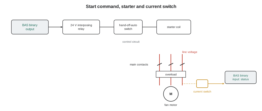
The controls technician's work stops at the starter's control circuit. The BAS usually closes a contact in series with the starter's coil, often through a hand-off-auto (HOA) switch, so that the fan can be run by hand for maintenance, stopped, or left to the BAS. The motor's power wiring, the starter, the overload relay and the disconnect are line-voltage work for a licensed electrician. Control circuits inside starters may be 120 V or 24 V; even where the BAS contact is low voltage, the enclosure holds lethal voltages, and work inside it needs the same lockout and testing practice as any electrical panel.
Why status must be proven separately
A start command tells the controller what it asked for, not what happened. The fan might not start because the HOA switch is in off, the overload has tripped, the disconnect is open, the drive has faulted, or the starter's coil has failed. Even when the motor runs, the fan may not move air because a belt has broken or a coupling has failed. Every important motor in a building therefore has a separate status input, and the controller compares status with command. A command on with status off for more than a short delay is a failure alarm; command off with status on means the equipment is running in hand or a contact has welded shut.
Several devices can provide status, each proving something different. A starter auxiliary contact proves that the starter pulled in, not that the motor turns. A drive's run contact proves the drive is outputting power. An airflow switch, a differential pressure switch across the fan, proves that air is actually moving. A current switch, which senses the current in the motor leads, proves that the motor is drawing current. That last is the most common, because it is easy to install, but by itself it cannot tell the difference between a motor driving a fan and a motor spinning freely with no belts, unless it is set up to do so.
| Status device | What it proves | What it can miss |
|---|---|---|
| Starter auxiliary contact | The starter coil pulled in | Tripped overload, failed motor, broken belt |
| Drive run contact | The drive is outputting power | Broken belt or coupling |
| Current switch, fixed or loosely set | The motor is drawing current | Broken belt, unless the setpoint is set above no-load current |
| Current switch set for belt loss | The motor is loaded normally | A partly slipping belt |
| Airflow or differential pressure switch | Air is moving across the fan | Low but nonzero airflow |
Current switches and current transmitters
A current switch is a small device with a hole or a hinged core through which one of the motor's power conductors passes. The current in the conductor induces a small current in a coil inside the device, the way a transformer works, and the device closes a contact when that current exceeds its trip point. It is powered by the current it senses, so it needs no separate supply. Solid-core types need the conductor disconnected and threaded through; split-core types open on a hinge and clamp around the conductor without disconnecting anything, which makes them popular for retrofits. Only one conductor goes through the hole: passing two conductors of the same circuit cancels the field and the switch sees nothing.
Current switches come in three kinds of setpoint. Fixed-trip switches close at a set low current, such as a fraction of an amp, and prove only that some current flows. Adjustable switches have a trip point that the technician sets with a potentiometer. Self-calibrating switches learn the motor's normal current and trip on a change from it. A current transmitter is the analog version: it reports the actual current as 0 to 10 V or 4 to 20 mA, so the BAS can trend it and apply its own alarm limits, and it can reveal slipping belts, clogged filters and other changes in load.
Setting a current switch for belt loss
A motor running with no load still draws current to magnetize its iron and overcome its own friction, often somewhere around a third to a half of its full load current for a typical induction motor. A current switch with a low fixed trip point closes for both the loaded and the unloaded motor, so a broken belt goes unnoticed. To detect belt loss, the trip point must sit between the motor's no-load current and its normal running current.
Worked problem
Setting EF-3's current switch
EF-3's motor nameplate shows a full load current of 14 A. With new belts, Callie measures 11.5 A at the motor with the fan running normally. With the belts removed, the motor draws 5.6 A. Where should the adjustable current switch trip?
Show solution
- No-load current: 5.6 A, about 40 in 100 of full load.
- Normal running current: 11.5 A.
- A trip point roughly midway, about 8.5 A, closes only when the fan is loaded and opens if the belts break.
Answer: About 8.5 A. The switch must be set with the fan running normally and tested by watching the status as the motor runs unloaded, or by following the manufacturer's setup procedure.
EF-3's switch was a fixed-trip model with a trip point well below the motor's no-load current, so the controller had seen a running fan while the belts lay in the housing. After the mechanic fitted new belts, Callie installed an adjustable split-core switch on the same lead, set it to 8.5 A as the example shows, and checked it with Prakash: at the disconnect, with the belts off for the test, the status dropped to off within a few seconds of the motor reaching speed. They refitted the belts and the status returned to on. For the lab exhaust fans, Prakash also recommended adding an airflow switch, because a fume hood exhaust fan's job is moving air, and proof of airflow is a better match for that job than proof of current.
Variable frequency drives complicate current sensing. A drive's output current changes with speed, so a fixed trip point that suits full speed may be below the motor's current at low speed, and a current switch on the motor leads sees a distorted waveform. Current switches on drives should be types rated for drive outputs, mounted where the manufacturer says, or replaced by the drive's own status and fault outputs, which report broken belts through the drive's load monitoring if that feature is set up.
Checking relays, contactors and current switches
- A relay that does not pull in: check for coil voltage at the coil terminals while commanded. Voltage present means a failed coil; no voltage means a problem upstream, at the controller output, its fuse or the transformer.
- A relay that pulls in but the load does not run: check the contacts with power removed and the circuit isolated, or measure across them live with appropriate care: a closed contact should show near zero volts across it.
- Contactors that chatter: low coil voltage, often from an undersized control transformer or a loose connection.
- A current switch that never closes: check that only one conductor passes through it, that the motor actually draws current above the trip point, and that the switch is wired to the controller's input correctly.
- A current switch that never opens: check its trip point against the motor's no-load current.
- Any work inside a starter or drive enclosure: follow lockout procedures and test for absence of voltage first.
Solid-state relays and relay timing
Some panels use solid-state relays instead of electromechanical ones. A solid-state relay switches its load with semiconductors instead of moving contacts, so it has no contacts to wear or bounce and can switch very frequently and silently. It suits electric heater staging and other loads that cycle often. Solid-state relays have their own cautions: they leak a small current when off, which can keep a sensitive load such as a small relay coil or an indicator partly energized; they produce heat and may need a heat sink; and they usually fail shorted, leaving the load on. A load that will not switch off fully after a relay change may be seeing this leakage.
Timing also matters when relays sit in safety and status circuits. A contactor takes a fraction of a second to pull in, and a motor takes several seconds to reach speed and draw its normal current, so a BAS status alarm needs a delay after a start command before it compares command with status. Too short a delay gives false failure alarms at every start; too long a delay lets a real failure go unnoticed. Sequences commonly use a delay of somewhere between 15 and 60 seconds for fans, set to suit the equipment, and drives with long ramp times need longer.
Common mistakes
MistakeUsing a fixed low-trip current switch to prove a belt-driven fan.
InsteadUse an adjustable or self-calibrating switch set between no-load and running current, or an airflow switch.
MistakePassing two conductors of the same circuit through a current switch.
InsteadPass only one conductor; the fields of two cancel.
MistakeTreating a starter auxiliary contact as proof the fan moves air.
InsteadUse current or airflow proof for that.
MistakeWiring a controller output straight to a starter coil without checking voltage and current.
InsteadUse an interposing relay rated for the coil circuit.
MistakeWorking in a starter enclosure because the BAS wiring is only 24 V.
InsteadLock out and test; the enclosure holds line voltage.
MistakeSetting current switches on drive outputs as if they were across-the-line motors.
InsteadUse drive-rated switches or the drive's own status outputs.
Summary and key terms
- Relays let low-voltage outputs switch other circuits; they are rated by coil voltage, contact form and contact rating.
- Contactors switch power loads; motor starters add overload protection; the BAS works through the control circuit.
- Status must be proven separately from the command, and each status device proves something different.
- Current switches sense motor current through one conductor; split-core types clamp on without disconnecting.
- To detect belt loss, set the trip point between no-load and normal running current.
- Current transmitters report actual current and can reveal slipping belts and changing loads.
- Relay
- An electrically operated switch with a coil and separate contacts.
- Interposing relay
- A relay between a controller output and a load or circuit the controller cannot switch directly.
- SPDT
- Single-pole double-throw: a common contact with normally open and normally closed contacts.
- Contactor
- A heavy-duty relay for switching power circuits.
- Motor starter
- A contactor with an overload relay that protects the motor.
- Hand-off-auto (HOA) switch
- A selector that runs equipment by hand, stops it, or leaves it under automatic control.
- Current switch
- A device that closes a contact when the current in a conductor passing through it exceeds a trip point.
- Current transmitter
- A device that reports the current in a conductor as an analog signal.
Practice problems
Work each problem on paper first, then reveal the answer to check.
A motor draws 18 A loaded and 7 A with no belts. Where should a belt-loss current switch trip?
Show answer
Between 7 and 18 A, about 12.5 A.
What does a starter auxiliary contact prove?
Show answer
That the starter's coil pulled in, not that the motor turns or the fan moves air.
A relay coil is commanded on but has no voltage at its terminals. Where is the fault?
Show answer
Upstream: the controller output, its fuse, the wiring or the transformer.
Why must only one conductor pass through a current switch?
Show answer
Current in two conductors of the same circuit flows in opposite directions and cancels the field.
What alarm should the BAS raise when a fan is commanded on but its status stays off?
Show answer
A failure alarm after a short delay.
Lesson quiz · 5 questions
Score 60% or more to complete this lesson.
Create a free account to save your progress, take quizzes and earn a certificate.