
ROOF-310 · Lesson 4 of 12 · 27 min
Attaching insulation
▶ Video coming soon A video version of this lesson is on the way.
At seven on the morning of Monday, November 9, the air over the Carrick Street roof was just above freezing and the old membrane was damp with dew. By nine, Dana's crew had stripped the first bay to the steel deck and rolled the primed self-adhered air and vapour barrier across it. Then they stopped. Priya Natt had pointed an infrared thermometer at the barrier and read 3 °C. The low-rise foam adhesive the roof type called for, a cold-weather grade, could go down at a surface temperature of 4 °C or more by its data sheet, and not lower. "We wait twenty minutes and read it again," Dana said. At 9:15 the sun was on the roof and the barrier read 6 °C, and the first bead went down.
Insulation has to stay where it is put, in every wind the building will see, for the life of the roof. This lesson covers the ways insulation and cover boards are attached, how attachment patterns are set for wind zones, how fastener length and quantity are worked out, how adhesives are applied and what limits them, and how tested assemblies and uplift ratings tie it together. Membrane attachment was covered in ROOF-210 and ROOF-220.
Why attachment matters
Wind blowing over a roof lowers the pressure above it, and air leaking into the building can raise the pressure below it. Together they try to lift every layer. If any layer lets go, everything above it goes with it: a roof with a perfectly fastened membrane will still blow off if the boards it is fastened through are only lying loose on a deck, or if the cover board's bond to the insulation fails. The wind pulls hardest at the corners, then along the perimeter, and least in the middle of the roof, so attachment is heavier in those zones (ROOF-120).
Attachment also keeps boards flat. A board that curls or rocks on the deck stresses the membrane, makes a soft spot that cracks under foot traffic, and opens gaps that leak air and heat.
The main attachment methods
| Method | How it works | Where it is used | Limits |
|---|---|---|---|
| Mechanical fasteners and plates | Screws through each board into the deck, with a large plate under the head | Steel and wood decks; base layers | Thermal bridges; deck must hold the screw |
| Low-rise foam adhesive | Two-part foam applied in beads or ribbons; boards set into it and weighted | Over concrete, barriers and lower boards | Temperature, moisture and open-time limits |
| Hot asphalt | Boards set into mopped asphalt | Bituminous systems | Not over polystyrene; board size limits |
| Cold adhesive | Solvent or water-based adhesive in beads or spread | Some single-ply and recover systems | Cure time; compatibility with the board |
| Loose-laid under ballast | Weight of stone or pavers holds everything | Ballasted and protected membrane roofs | Wind zones and roof height limits |
In many systems the methods are combined. A common pattern on steel decks is to fasten the first layer mechanically and adhere the upper layers and the cover board, so the fasteners are buried under unbroken boards. On the Westlane clinic addition later that week, the single layer of polyiso and the gypsum cover board were held only by the base sheet fasteners, which passed through both boards into the deck. That works when the assembly has been tested that way.
Mechanical fasteners and plates
Insulation fasteners are coated, hardened steel screws with drill or sharp points, sized for the deck. On steel deck they must pass through the top flange of the deck by a minimum amount, commonly about 19 mm, set by the fastener maker and the system listing. The plate, usually round or square and about 75 mm across, spreads the load so the board does not pull over the screw. Fasteners on concrete and wood decks are different products and need pull-out tests on re-roofs.
Fasteners are driven with a stand-up screw gun that sets them to the right depth. An underdriven screw leaves the plate standing proud, which punctures the membrane or shows as a bump; an overdriven screw crushes the board and may strip out of the deck. Every fastener must land in the top flange of a steel deck, not over a flute, which means the installer must know which way the flutes run under the boards.
Worked problem
Fastener length for the Northgate base layer
Martin's Northgate design calls for two flat base layers of 50 mm polyiso fastened through both layers into the steel deck, with at least 19 mm penetration through the top flange. Fasteners come in 102, 114, 127 and 152 mm lengths. Which length should be used?
Show solution
- Thickness to pass through = 50 + 50 = 100 mm.
- Minimum length = 100 + 19 = 119 mm.
- The 114 mm fastener is too short; use 127 mm.
Answer: 127 mm, which passes through the flange by 27 mm. A fastener much longer than needed costs more and can strike conduit or ducts hung just below the deck.
Fastening patterns and zones
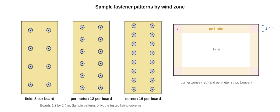
The number of fasteners per board comes from the tested assembly listing for the wind uplift the roof needs, and it increases in the perimeter and corner zones. The widths of the zones come from the design wind calculation, the code and the listing; on many Ridgecap jobs they are 2.4 m wide. A typical pattern on 1.2 by 2.4 m boards from one maker's listing might be 8 fasteners per board in the field, 12 in the perimeter and 16 in the corners, laid out in a grid so the plates are evenly spaced and kept a set distance from the board edges. Real patterns vary, and the listing governs.
Worked problem
Counting fasteners for the Northgate base layer
Northgate's roof is 50 m by 28 m. With 2.4 m perimeter and corner zones and the sample pattern of 8, 12 and 16 fasteners per 1.2 by 2.4 m board, how many base-layer fasteners are needed, before waste?
Show solution
- Roof area = 50 × 28 = 1,400 m². Corners = 4 × 2.4 × 2.4 = 23.04 m².
- Perimeter strips = 2 × (50 − 4.8) × 2.4 + 2 × (28 − 4.8) × 2.4 = 216.96 + 111.36 = 328.32 m².
- Field = 1,400 − 328.32 − 23.04 = 1,048.64 m².
- Board area = 1.2 × 2.4 = 2.88 m². Boards: field 364.1, perimeter 114.0, corners 8.0.
- Fasteners = 364.1 × 8 + 114.0 × 12 + 8.0 × 16 = 2,913 + 1,368 + 128 = 4,409.
Answer: About 4,400 fasteners and plates, plus a few in 100 for waste. Only one set is needed for the two base layers, because both are fastened together.
Worked problem
How hard does the wind pull on one fastener?
Suppose the design uplift in a corner zone is 2.4 kPa and each 2.88 m² corner board has 16 fasteners. What load does each fastener carry, and how does that compare with the 2.2 kN pull-out measured on dry Northgate screws in the spring?
Show solution
- Area per fastener = 2.88 ÷ 16 = 0.18 m².
- Load = 2.4 × 0.18 = 0.432 kN.
- 2.2 ÷ 0.432 = 5.1.
Answer: Each fastener carries about 0.43 kN, about a fifth of its dry pull-out. The rusted screws at Northgate held only 0.9 kN, which cuts that margin by more than half; this is why wet insulation is a wind problem as well as a thermal one.
Adhesives
Low-rise foam adhesive is a two-part polyurethane supplied in cartridges, bag-in-box packs or bulk containers and dispensed from a cart or hand tool in beads that expand slightly and set within minutes. The boards are laid into the wet beads, walked in, and weighted so they stay in contact as the foam rises and sets. The listing sets the bead spacing by zone; a typical pattern is a bead every 300 mm in the field, 150 mm in the perimeter and 100 mm in the corners. Adhesives fill small irregularities in the surface and leave no fastener heads to bridge heat, which is why they are used for the upper layers and cover boards.
Every adhesive has limits that the crew must respect:
- Surface and air temperature: below the minimum on the data sheet, the foam rises poorly and bonds weakly. Cold-weather grades extend the range, and the containers themselves must be kept warm.
- Moisture: the surface must be dry; frost, dew and standing water ruin the bond.
- Open time: boards must be set before the foam skins over, so beads are run only a little ahead of the board setters.
- Board size: adhered boards are often limited to 1.2 by 1.2 m so they lie flat; larger boards curl and lift at the corners.
- Compatibility: some adhesives and primers attack polystyrene, and not every adhesive is accepted over every barrier or board.
Boards are set with tight joints and walked in by stepping along each one. On Carrick Street, the crew put two pails of fasteners on each new board as weights until the foam set, and Priya lifted the corner of a board every hour or so to check that the foam had bonded to both surfaces. A board that lifts easily with a little wet foam on only one side has not bonded and must be reset.
Worked problem
Bead length for one layer at Carrick Street
The Carrick Street roof is 38 m by 20 m (760 m²) with 2.4 m perimeter and corner zones. With beads every 300 mm in the field, 150 mm in the perimeter and 100 mm in the corners, how many metres of bead are needed for one layer?
Show solution
- Corners = 4 × 2.4 × 2.4 = 23.04 m². Perimeter = 2 × (38 − 4.8) × 2.4 + 2 × (20 − 4.8) × 2.4 = 159.36 + 72.96 = 232.32 m².
- Field = 760 − 232.32 − 23.04 = 504.64 m².
- Bead per m²: field 1 ÷ 0.30 = 3.33 m, perimeter 1 ÷ 0.15 = 6.67 m, corner 1 ÷ 0.10 = 10 m.
- Total = 504.64 × 3.33 + 232.32 × 6.67 + 23.04 × 10 = 1,682 + 1,549 + 230 = 3,461 m.
Answer: About 3,460 m of bead for one layer. Carrick Street has three adhered interfaces (second insulation layer, tapered crickets and cover board are set in foam over the first layer and the barrier), so the estimator multiplies by the number of adhered layers and checks the yield on the adhesive's data sheet.
Hot asphalt and other methods
On built-up and modified bitumen roofs, insulation is sometimes set in a full mopping of hot asphalt (ROOF-210). The boards must be ones the maker accepts for hot asphalt, the asphalt must be at the right temperature at the point of application, and the boards are usually limited in size and walked in immediately. Polystyrene can never be set in hot asphalt. Ballasted and protected membrane roofs hold insulation down by weight alone (lesson 7 and ROOF-220), within the wind and height limits of their design standard. Induction-welded single-ply systems fasten plates through the insulation and then weld the membrane to the plates from above, leaving the membrane unpierced.
Tested assemblies and uplift ratings
Roofers do not choose fastener patterns or bead spacings; the tested assembly does. In Canada, the Ontario Building Code requires membrane roofing systems to be tested for wind uplift resistance to CSA A123.21, a dynamic test that cycles suction on a full-size sample of the whole assembly, from the deck up, or to show proven past performance. The membrane maker publishes the tested assemblies and the resistance each achieved, and the designer picks one that meets the building's design wind pressure from Part 4 of the code. The listing specifies every component: deck type and gauge, board types and thicknesses, fastener and plate types, the pattern by zone, adhesives and bead spacing, and the membrane and its attachment. Changing any one of them changes the assembly.
That is why substitutions matter. When a supplier offered a cheaper cover board for Carrick Street, Glen asked the membrane maker's technical representative whether it appeared in the tested assembly. It did not, so it was not used.
Thermal bridging by fasteners
Each fastener is a small steel path for heat through the insulation. One screw does little, but thousands add up, and on a cold morning the plates sometimes show as a pattern of frost spots on a membrane fastened through a single layer. Burying the fasteners under an adhered upper layer, or using fewer but larger boards in the fastened layer, reduces the effect. Energy calculations can allow for fasteners (lesson 11).
Checking attachment on the job
- Read the listing and the roof type before starting; carry the pattern sketch on the roof.
- Mark the zones on the deck or base layer with paint or chalk.
- Check that fasteners penetrate the deck by the required amount; on re-roofs, run pull-out tests as the maker requires.
- Check adhesive temperature, surface temperature and dryness before each start and after breaks.
- Lift sample boards to confirm the bond, and record the checks in the daily report with photos.
At the end of Monday, before the cover board went on over the last bay, Dana lifted three boards at random and photographed the foam on both sides of each for the daily report. "Contact on both faces at every bead," she wrote. "That's what the maker's rep will ask about on Friday."
Common mistakes
MistakeApplying adhesive below its minimum temperature or on a damp surface.
InsteadRead the surface temperature and dryness, and wait or switch to a cold-weather grade.
MistakeUsing the field fastener pattern in the corners.
InsteadIncrease the pattern in perimeter and corner zones as the listing requires.
MistakeDriving fasteners over the deck flutes or to the wrong depth.
InsteadLand every screw in a top flange and set the plate flush.
MistakeSubstituting a board, fastener or adhesive that is not in the tested assembly.
InsteadCheck with the maker and the designer before any change.
MistakeLeaving adhered boards unweighted while the foam sets.
InsteadWalk boards in and weight them until the adhesive has set.
Summary and key terms
- Attachment keeps every layer in place against wind uplift and keeps boards flat.
- The main methods are fasteners and plates, low-rise foam, hot asphalt, cold adhesive and ballast, often combined.
- Fasteners must pass through every layer and into the deck by the required amount.
- Patterns and bead spacings increase in perimeter and corner zones and come from the tested assembly.
- Adhesives have temperature, moisture, open-time and compatibility limits.
- Uplift testing and listings tie every component together; substitutions change the assembly.
- Insulation fastener
- A coated screw that holds insulation boards to the deck, used with a plate.
- Insulation plate
- A large round or square plate under a fastener head that spreads the load.
- Low-rise foam adhesive
- A two-part polyurethane foam applied in beads to bond insulation and cover boards.
- Open time
- The time after application during which an adhesive will still bond.
- Wind zone
- A field, perimeter or corner area of a roof with its own design uplift.
- Tested assembly
- A complete roof system that has passed a wind-uplift test with specified components.
- Pull-out test
- A field test that measures the force needed to pull a fastener from the deck.
- Thermal bridge
- A path through the insulation, such as a steel fastener, that conducts heat more readily.
Practice problems
Work each problem on paper first, then reveal the answer to check.
Two layers of 64 mm insulation are fastened with 19 mm minimum penetration. What is the minimum fastener length?
Show answer
64 + 64 + 19 = 147 mm.
Why are upper layers and cover boards often adhered rather than fastened?
Show answer
To bury the fasteners and avoid thermal bridges and plate bumps.
A corner board of 2.88 m² has 16 fasteners and a design uplift of 3.0 kPa. What load does each carry?
Show answer
2.88 ÷ 16 = 0.18 m²; 3.0 × 0.18 = 0.54 kN.
Name three limits on low-rise foam adhesive.
Show answer
Temperature, moisture and open time; also board size and compatibility.
What does a CSA A123.21 test measure?
Show answer
The wind uplift resistance of a full roof assembly under cycling suction.
Lesson quiz · 5 questions
Score 60% or more to complete this lesson.
Create a free account to save your progress, take quizzes and earn a certificate.