
ROOF-310 · Lesson 1 of 12 · 21 min
The roof assembly as a system
▶ Video coming soon A video version of this lesson is on the way.
On the third Tuesday of October, Glen Pelham opened the training room at the Ridgecap yard at six in the evening for the first of the fall study nights. He had started them for apprentices heading into their next block of trade school, and Rory Quintero, Keisha Grant and two apprentices from the single-ply crew sat at the long table with coffee while Dana Renaud drew on the whiteboard. She drew a steel deck, then a line above it, then two thick layers, then a thin layer, then the membrane. "Everyone in this room can put a membrane down," she said. "This fall we're going to talk about everything under it, and about where the water goes once it's on top. Most roofs that fail early fail because somebody treated those layers as filler."
This lesson introduces the low-slope roof assembly as one system. It names the layers, explains what each does, shows how they depend on each other and on the building below, and sets up the rest of the course: insulation boards (lesson 2), tapered insulation (lesson 3), attachment (lesson 4), vapour and air control (lessons 5 and 6), protected membrane roofs (lesson 7), drainage (lessons 8 to 10), energy codes (lesson 11) and a tapered design case study (lesson 12). Flashings and details are covered in ROOF-320.
What a roof assembly is
A roof assembly is everything from the underside of the structural deck to the top of the surfacing. On a typical Hamilton commercial roof, from the bottom up, that means:
- The structural deck: steel, concrete, wood or, on older buildings, gypsum or cementitious wood fibre.
- A thermal barrier or substrate board, where the code or the system requires one over a steel deck under foam insulation.
- An air barrier and vapour retarder, often one self-adhered sheet that does both jobs.
- Insulation, usually in two or more layers with staggered joints, and sometimes tapered to create slope.
- A cover board that protects the insulation and gives the membrane a firm, smooth surface.
- The membrane: built-up, modified bitumen or single-ply, as covered in ROOF-210 and ROOF-220.
- Surfacing: granules, gravel, coatings, or ballast and pavers.
Around and through those layers are the parts that complete the system: roof drains and their sumps, scuppers, edge metal, parapet flashings, curbs, pipe penetrations and walkway pads. A roof is only as good as the worst of these. Dana's whiteboard rule was blunt: "A roof isn't a membrane. It's a membrane on a stack, on a building, in a climate."
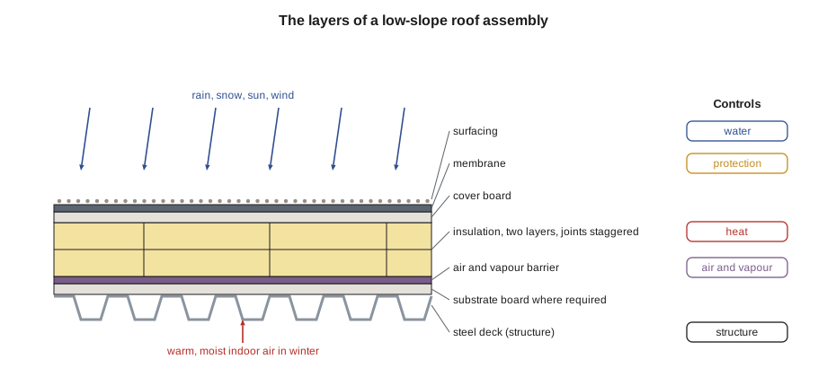
The four things a roof controls
Building scientists describe every part of the building enclosure by what it controls. For a roof, there are four control layers, and every assembly needs all four in an unbroken line:
| Control | Main layer on a low-slope roof | What failure looks like |
|---|---|---|
| Water | The membrane and its flashings, plus slope and drains | Leaks, wet insulation, ponding |
| Air | An air barrier on the deck, sealed to the wall air barrier | Condensation under the membrane, heat loss, wind uplift from inside |
| Vapour | A vapour retarder on the warm side of the insulation, where needed | Slow moisture build-up in the insulation |
| Heat | The insulation layers, with as few thermal bridges as possible | High energy use, ice at eaves, condensation at cold spots |
The membrane controls water from outside. It is also, by its nature, a near-perfect vapour barrier, which is why moisture that gets into the roof from below has no easy way out (lesson 5). The air barrier stops warm indoor air from carrying moisture into the insulation and from pressurizing the underside of the membrane in a windstorm. The insulation controls heat, and its thickness sets where in the assembly the cold surfaces are. Slope and drains are part of water control too: a membrane that sits in water for days wears faster and leaks sooner through any small defect.
These layers interact. Adding insulation makes the membrane colder in winter, so any moist air that reaches its underside condenses more readily. A white, reflective membrane keeps the roof cooler in summer but also slows the drying of a damp assembly. A tapered insulation system that creates slope changes the height of every curb, drain and flashing on the roof. Change one layer, and you have changed the system.
The deck sets the rules
The deck is the base of the system, and its type decides much of what goes above it:
- Steel deck: the most common on Hamilton commercial buildings. Its flutes leave gaps under the first board, so boards must span the flutes and be wide enough to bear on the top flanges. Insulation is usually fastened with screws and plates into the top flanges, or adhered to a board that is itself fastened. Steel decks are not airtight: air moves through the side laps and end laps of the deck sheets and through every opening cut in them.
- Concrete deck: heavy, airtight in itself and a good base for adhered systems. It must be dry before adhesives or hot asphalt are applied, and new concrete can carry a great deal of construction moisture for months.
- Wood deck: plywood, OSB or planks. Fastening is easy, but torch work and hot work over wood are restricted (ROOF-210), and old plank decks can have gaps that let air through.
- Gypsum, cementitious wood fibre or lightweight concrete fill: found on older buildings; fasteners and adhesives must be the ones the maker approves for that deck, and pull-out tests are usually required.
Every assembly the designer chooses has to be tested or approved for that deck. A system listed for wind uplift over steel deck is not automatically approved over wood or concrete (lesson 4).
Why the layers fail together
When Ridgecap investigated the Northgate Medical Building blow-off in the spring (ROOF-120), the cause was not one bad layer. The corners had been fastened like the field, and the edge metal had not been a tested system, but the roof also had no air barrier, a single layer of insulation with straight joints, and a sagging bay that ponded water. Warm, humidified air from the dental suite and laboratory had leaked up through the deck and soaked about 180 m² of insulation from below. The wet insulation had rusted the fasteners, and the rusted fasteners held less than half of what dry ones did. The roof failed at the corner in the storm, but it had been failing from inside for years.
Dana listed the lessons from Northgate on the board, one for each layer:
- Air barrier missing: indoor air carried moisture into the insulation.
- One insulation layer with straight joints: air moved through the joints, and every joint was a line of heat loss.
- No cover board: the polyiso facer under the membrane was crushed where people walked to the rooftop units.
- No slope: the deck had sagged at one bay and water stood for days after rain.
- Wet insulation: the fasteners rusted and lost their grip.
"Look: nothing on that list is about the membrane," Dana said. "The TPO was fine. Everything under it let it down."
Reading an assembly on a drawing
Roof assemblies are shown on drawings as a section and a written list of layers, usually called a roof type, with a tag such as R1 or R2 that appears on the roof plan. The specification gives the products, standards and installation requirements. Before a job starts, the foreperson reads the roof type, the plan and the specification together and checks four things:
- Thickness: does the total build-up match the heights of the curbs, drains, door sills and parapets on the roof? A roof that rises 150 mm can bury a door threshold or a roof hatch curb.
- Compatibility: are the adhesives, boards and membrane all from one approved system, or at least accepted by the membrane maker for the warranty?
- Attachment: what holds each layer down, and does the method suit the deck and the wind zones?
- Continuity: how does the air barrier on the roof connect to the wall air barrier at the parapet, and how is it sealed at every penetration?
On the Carrick Street office re-roof scheduled for early November, the roof type read, from the bottom: steel deck; primed, self-adhered air and vapour barrier; two layers of 75 mm polyiso, joints staggered, set in low-rise foam adhesive, with tapered crickets between the drains; 13 mm glass-mat gypsum cover board, primed; self-adhered SBS base; torch-applied SBS cap. Dana made Rory read it aloud and explain each layer, then asked him what would happen if the crew forgot the primer under the self-adhered barrier on a cold morning. "It won't stick," Rory said. "And if the barrier doesn't stick, it isn't a barrier."
Heat flow through an assembly
Insulation is rated by its thermal resistance: RSI, in m²·K/W. Resistances of layers in series add up, like links in a chain. The total includes the thin films of still air on each surface, which add a little resistance. The heat that flows through each square metre of roof is the temperature difference divided by the total resistance, which is the same as the temperature difference times the U-value, where U is one divided by the total resistance:
Thin layers such as the membrane, the barrier and the deck add almost nothing to the total; the insulation does nearly all the work. That is why designers count mainly the insulation, and why every gap, crushed board or wet patch in it matters.
Worked problem
Heat loss through the Carrick Street roof
The Carrick Street roof is 760 m². The assembly has two layers of 75 mm polyiso at a typical design value of RSI 1.0 per 25 mm, a 13 mm gypsum cover board at RSI 0.08, an inside air film of RSI 0.11 and an outside film of RSI 0.03. Find the total RSI, the U-value and the heat loss on a night when it is 21 °C inside and −10 °C outside.
Show solution
- Insulation = 150 ÷ 25 × 1.0 = RSI 6.0.
- Total = 6.0 + 0.08 + 0.11 + 0.03 = RSI 6.22.
- U = 1 ÷ 6.22 = 0.161 W/m²·K.
- Heat loss = 0.161 × 760 × (21 − (−10)) = 0.161 × 760 × 31 = 3,793 W.
Answer: About 3.8 kW through the whole roof on that night, roughly what two small electric heaters use. The insulation provides 6.0 of the 6.22, which is why designers focus on it.
The example assumes the insulation is dry, continuous and at its rated value. In the real roof, the screws, plates, drain sumps and edges let a little extra heat through, and polyiso loses some of its value when it is very cold (lesson 2). Lesson 11 shows how codes allow for this.
The roofer's part in the system
Designers draw the assembly; roofers build it, and most of what makes it work is installation. A system can have the right products in the right order and still fail because:
- Boards were laid with open joints, or with joints lined up from one layer to the next, so heat and air short-circuit through the gaps.
- The air barrier was not sealed at the parapet, the curbs and the deck openings, so air walks around it.
- Insulation was installed wet, or left uncovered overnight and rained on, then sealed in under the membrane.
- Fasteners were too short to grip the deck, or too few in the perimeter and corners.
- Tapered panels were laid in the wrong order, so the slope runs the wrong way in part of the roof.
- Adhesive was applied below its temperature limit, or the boards were not walked in or weighted while it set.
Ridgecap's rule is that no more insulation is laid in a day than can be covered with at least the base ply or a temporary seal before the crew leaves. Night seals at the edge of each day's work keep water out of the boards already laid (ROOF-210). A wet board is cut out and replaced, not covered.
How the rest of this course fits
Each later lesson takes one part of the system and goes deeper. Lessons 2 to 4 cover the boards, the slope they can create and how they are held down. Lessons 5 and 6 cover air and vapour, the main cause of the Northgate damage. Lesson 7 turns the usual order upside down with the protected membrane roof. Lessons 8 to 10 follow the water off the roof through drains, scuppers, gutters and downspouts, and explain what happens when it does not leave. Lesson 11 connects the insulation to the energy codes, and lesson 12 puts it all together in Martin Oyelaran's tapered design for the Northgate re-roof.
By the end of the evening, the whiteboard was covered. Dana circled the bottom of her drawing. "Next week, the boards," she said. "Bring the label off anything you laid this month."
Common mistakes
MistakeTreating insulation, barriers and cover boards as filler under the membrane.
InsteadBuild each layer to the specification; most early failures start under the membrane.
MistakeLining up the joints of two insulation layers.
InsteadStagger the joints by at least 300 mm or as the system requires.
MistakeLeaving the air barrier unsealed at parapets and curbs.
InsteadSeal it to the wall air barrier and around every penetration.
MistakeCovering wet insulation.
InsteadCut out and replace wet boards, and night-seal each day's work.
MistakeIgnoring the total thickness of a new assembly.
InsteadCheck curbs, drains, door sills and parapet heights against the build-up before the job starts.
Summary and key terms
- A roof assembly runs from the deck to the surfacing and must be designed and built as one system.
- Every roof needs continuous control of water, air, vapour and heat.
- The deck type sets the attachment methods and much of what can go above it.
- Layers fail together: missing air barriers, single insulation layers and ponding can ruin a sound membrane.
- Thermal resistances in series add; U is one divided by the total, and heat loss is U times area times temperature difference.
- Most of what makes an assembly work is careful installation.
- Roof assembly
- All layers of a roof from the underside of the deck to the top of the surfacing.
- Control layer
- A layer that controls the flow of water, air, vapour or heat through the enclosure.
- Air barrier
- A continuous layer that stops air from moving through the assembly.
- Vapour retarder
- A layer that slows the diffusion of water vapour through the assembly.
- Cover board
- A thin, firm board laid over insulation to protect it and support the membrane.
- Thermal resistance
- A measure of how well a layer resists heat flow; resistances in series add.
- U-value
- The rate of heat flow through one unit of area for each degree of temperature difference; one divided by the total resistance.
- Roof type
- The tagged list of layers for one assembly on a drawing, such as R1.
Practice problems
Work each problem on paper first, then reveal the answer to check.
Name the four control layers of a roof.
Show answer
Water, air, vapour and heat.
Two insulation layers each have RSI 3.0 and the other layers and films add RSI 0.22. What is the U-value?
Show answer
1 ÷ 6.22 = 0.161 W/m²·K.
Why is a steel deck not an air barrier?
Show answer
Air moves through its side laps, end laps and openings.
Why stagger insulation joints?
Show answer
So air and heat cannot pass straight through lined-up gaps.
What should happen to an insulation board that got rained on before it was covered?
Show answer
It is cut out and replaced, not covered.
Lesson quiz · 5 questions
Score 60% or more to complete this lesson.
Create a free account to save your progress, take quizzes and earn a certificate.