
ROOF-120 · Lesson 12 of 12 · 27 min
Case study: why a roof failed
▶ Video coming soon A video version of this lesson is on the way.
Two weeks after the April storm, Glen spread the Northgate Medical Building file across the boardroom table: the original 2014 drawings, the manufacturer's warranty, three years of service invoices from another contractor, dozens of photos and a stack of moisture readings. Dana, Anjali and Rory sat around it. "The building owner wants to know three things," Glen said. "Why did it fail? Was it just a freak storm? And what do they need to do so it doesn't happen again? We're going to answer all three, and Rory, you're going to see how every lesson this year shows up on one roof."
This final lesson follows a real-style investigation from the first call to the final report. Roof failures are almost never caused by one thing. Usually a chain of small decisions, shortcuts and missing pieces lines up until one event, often a storm, exposes them all. Learning to find that chain is how roofers stop repeating it.
The building and the roof
The Northgate Medical Building is a two-storey medical office built in 2014. It houses a family practice, a dental suite, a small laboratory and offices. In winter, the building's ventilation system humidifies the air to about 35 to 40 per cent relative humidity for patient comfort, and the dental suite and laboratory run sterilizers and other equipment that add moisture.
| Item | As found |
|---|---|
| Roof area | about 1,400 m² (about 15,000 ft²), low-slope, with one interior drain area and scuppers on the north side |
| Deck | galvanized steel deck, 0.76 mm (22 gauge), on steel joists |
| Air and vapour control | none on the deck; laps and perimeter unsealed |
| Insulation | one layer of polyiso, 90 mm (3.5 in), joints not staggered (single layer) |
| Membrane | 1.14 mm (45 mil) white TPO, mechanically attached in the seams |
| Edge | shop-made galvanized steel edge metal, face-nailed into a wood nailer, no continuous cleat |
| Rooftop units | two original units, plus a third added in 2019 near the middle of the roof |
| Maintenance | occasional repairs; drains cleared about once a year |
The failure
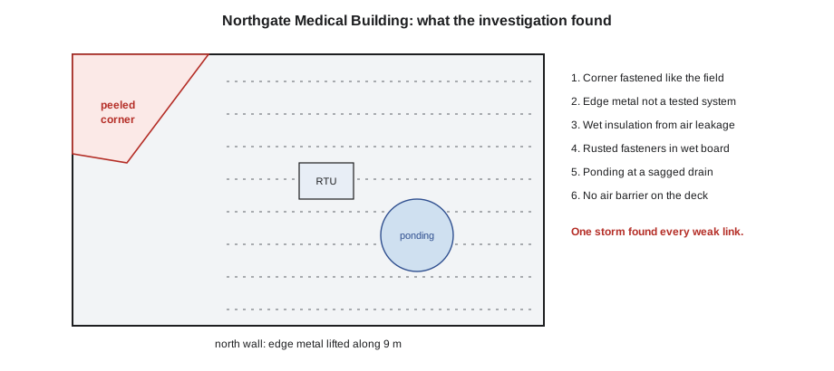
On the night of April 25 to 26, 2026, a spring windstorm brought gusts of about 100 km/h (62 mph) from the northwest. The roof's northwest corner peeled first. The edge metal along the north wall lifted over about 9 m (30 ft), wind got under the membrane, and a section of about 110 m² (1,200 ft²) tore loose, taking insulation boards with it. Rain entered the second-floor offices until Ridgecap's crew made the roof safe and dry the next morning, as described in lesson 10.
Other buildings in the area had lost shingles and a few signs, but most commercial roofs nearby came through without damage. That observation matters: a storm that strips one roof and leaves its neighbours alone usually points to a weakness in that roof, not just to the storm.
How the investigation was done
Ridgecap followed a standard sequence. It works for any failure, from a single leak to a blown-off roof:
- Make it safe and stop further damage, and photograph everything before it is disturbed.
- Collect the records: drawings, specifications, product data, the warranty, permits, service history, weather data and the owner's account of what happened.
- Survey the roof: walk the whole roof, mark every problem on a plan, and note what is not damaged as well as what is.
- Measure and test: make test cuts, take moisture readings, count and pull-test fasteners, measure ponding, check edge metal.
- Compare what was found with what was designed, what the manufacturer required and what the code requires.
- Build the chain of causes: for each finding, ask why it happened and how it contributed, until the root causes are clear.
- Report the findings and recommendations in writing, with photos and evidence.
Glen's rule is to keep facts and opinions separate. A photo of a rusted screw is a fact. "The screw rusted because the insulation was wet" is an opinion until the moisture readings and test cuts prove it.
Finding 1: the corners were fastened like the field
The 2014 drawings were clear: the membrane manufacturer's system called for half sheets in the perimeter and corners, with the same fastener spacing, to bring the fastener rows closer together where the wind suction is higher. On the roof, Dana and Rory counted the seams and fasteners. Full-width sheets ran right to the edges, with fasteners at the field spacing everywhere. The installer had saved time and material by skipping the half sheets.
Worked problem
How overloaded were the corner fasteners?
The original design gave an uplift of 1.1 kPa in the field and 2.6 kPa in the corners. Full sheets left 2.90 m between fastener rows, with fasteners every 300 mm. Half sheets would have left 1.375 m between rows. Find the load on each fastener in the field, in the corner as built, and in the corner as designed.
Show solution
- Field: 2.90 × 0.30 = 0.87 m² per fastener; 0.87 × 1.1 ≈ 0.96 kN.
- Corner as built: 0.87 m² per fastener; 0.87 × 2.6 ≈ 2.26 kN.
- Corner as designed: 1.375 × 0.30 ≈ 0.41 m² per fastener; 0.41 × 2.6 ≈ 1.07 kN.
- As built, each corner fastener carried 2.26 ÷ 0.96 ≈ 2.4 times the field load, and about twice what the design intended.
Answer: About 2.26 kN per corner fastener as built, against about 1.07 kN as designed. The corner had roughly half the wind resistance it was supposed to have from the day it was built.
That single shortcut explains why the failure started at a corner. The fact that the roof survived for 12 years only means it had not yet met a strong enough storm from the right direction.
Finding 2: the edge metal was not a tested system
The edge metal was bent from galvanized sheet in someone's shop and nailed through its face into the wood nailer at about 600 mm (24 in) spacing. There was no continuous cleat locking the bottom edge of the face, and the nailer itself was fastened to the wall with too few anchors. When the storm hit, the bottom of the face flexed outward, the wind caught it, and the nails pulled out of the nailer one after another. Once the metal lifted, the wind got under the membrane edge. As lesson 10 explained, this is the classic start of a low-slope blow-off.
The drawings had called for a manufactured edge system that had passed the wind test for the building's design pressure, with a continuous cleat. The substitution had never been approved.
Finding 3: wet insulation from inside
Ridgecap hired a roofing consultant to run an infrared scan of the roof on a cool, clear night. Wet insulation holds heat longer than dry insulation, so it shows up as warm patches on the scan after sunset. The scan showed a large warm area over the dental suite and laboratory, nowhere near any membrane damage. Dana and Rory confirmed it with a moisture meter and three test cuts. Under perfectly sound membrane and seams, the polyiso was soaked and the underside of the membrane was beaded with water. In total, about 180 m² (1,940 ft²) of insulation was wet.
The pattern matched lesson 4 exactly. Warm, humidified air from the dental suite and laboratory had leaked up through the unsealed laps and flutes of the steel deck and through the straight joints of the single insulation layer. In winter, it reached the cold underside of the membrane, far below its dew point, and condensed. Because the TPO membrane on top is itself a vapour barrier, the water could not dry out upward, and it built up year after year. A roof with an air and vapour barrier on the deck and two staggered insulation layers, as in lessons 4 and 5, would not have done this.
Glen pulled the service invoices. Three times in the past four years, the previous contractor had been called about drips from ceiling tiles in the dental suite in late winter. Each time, they had found no hole in the membrane, resealed a pipe boot, and left. They were fixing the wrong problem.
Finding 4: rusted fasteners in the wet zone
In the wet area, the membrane screws had rusted, and the steel deck around them showed surface rust. Field pull-out tests told the story in numbers: screws in the dry part of the roof held about 2.2 kN (500 lb) each, while screws in the wet area pulled out at about 0.9 kN (200 lb), less than half. The wet zone was not where the roof peeled this time, but it would have been the next place to go.
Finding 5: ponding at a sagging deck
Near the middle of the roof, a pond of water about 30 mm (1.2 in) deep and 25 m² (270 ft²) in area sat beside the drain two days after the storm. A level survey showed the deck had sagged near the third rooftop unit, added in 2019. There was no record of a structural review for the new unit or of new supports. The extra weight, plus the ponded water, had deflected the deck enough to tilt the area away from the drain.
Worked problem
The weight of the Northgate pond
The pond is about 30 mm deep over about 25 m². What does the water weigh, and what load does it add?
Show solution
- Volume = 25 × 0.030 = 0.75 m³.
- Weight ≈ 0.75 × 1,000 = 750 kg.
- Load = 750 ÷ 25 = 30 kg/m² (about 0.29 kPa).
Answer: About 750 kg, adding about 30 kg/m², right where the deck is already carrying the extra unit. Ponding feeds itself: more sag, deeper water, more sag. The engineer must review it.
Finding 6: what was not wrong
A good investigation also records what did not fail. The TPO membrane itself was in good condition, with plenty of thickness over the scrim. Most field seams probed tight. The drains, though dirty, were unobstructed. The steel deck outside the wet area was sound. The storm, while strong, was within the range the building code design expects for the area. Recording these points protects everyone from blaming the wrong thing: the membrane brand was not the problem, and neither was the weather alone.
Building the chain of causes
With the findings in hand, the team built the chain from the storm back to the root causes. Rory wrote it on the whiteboard:
| Link | What happened | Why | Lesson |
|---|---|---|---|
| 1 | Gusts hit the northwest corner and edge | normal spring storm, within design range | 10 |
| 2 | Edge metal lifted and pulled its nails | no continuous cleat; face-nailed; weak nailer anchorage | 8, 9, 10 |
| 3 | Wind entered under the membrane edge | edge no longer clamped the membrane | 10 |
| 4 | Corner sheet tore off its fasteners | full sheets, field spacing: about twice the design load per fastener | 9, 10 |
| 5 | Peel spread into the field | momentum of the lifted sheet; some weakened fasteners | 9, 10 |
| Background | Wet insulation and rusted fasteners over the dental suite | no air and vapour barrier; single insulation layer; humid interior | 4, 5 |
| Background | Ponding near the added unit | deck sag from added load without review | 1, 2, 3 |
The root causes were not the storm. They were three decisions made years earlier: skipping the half sheets, substituting untested edge metal, and leaving out an air and vapour barrier over a humid building. A fourth, adding a rooftop unit without a structural review, was setting up the next failure. Each saved a little money or time at the start. Together, they cost the owner a damaged second floor, a large repair and an early re-roof.
The repair
Ridgecap's repair ran from April 27 to May 8, 2026, under the manufacturer's supervision so the warranty could be restored for the repaired areas:
- Removed all wet insulation and the storm-damaged area down to the deck, about 290 m² (3,140 ft²) in total, and cleaned and primed the surface-rusted deck.
- Installed a self-adhered air and vapour barrier on the deck in the repaired areas, sealed at the laps and up the walls.
- Installed two layers of polyiso with staggered joints and a cover board, matching the overall thickness of the existing roof.
- Replaced the membrane in the repaired areas with half sheets in the perimeter and corners, fastened to the manufacturer's corner and perimeter pattern, and welded new to old after cleaning the weathered TPO.
- Refastened the corners and perimeters in the undamaged areas by adding new rows of fasteners under strips of membrane welded over them, as the manufacturer's repair detail allows.
- Re-anchored the wood nailers and installed a manufactured, tested edge system with a continuous cleat around the whole roof.
- Built a cricket of tapered insulation to steer water from the sagged area to the drain, as a temporary measure until the engineer's review.
Worked problem
How many insulation boards for the repair?
The repair covers 290 m² with two layers of polyiso in 1,220 × 2,440 mm boards. How many boards are needed with 5 per cent waste?
Show solution
- Board area = 1.22 × 2.44 ≈ 2.977 m².
- Boards per layer = 290 ÷ 2.977 ≈ 97.4, so 98.
- Two layers = 196 boards.
- With 5 per cent waste: 196 × 1.05 ≈ 205.8, so 206 boards.
Answer: 206 boards, plus cover boards and tapered pieces for the cricket.
The recommendations
Glen's report gave the owner a clear list:
- Have a structural engineer review the deck at the 2019 rooftop unit and add supports as needed.
- Plan a full re-roof within about two years (Ridgecap suggested summer 2028), with an air and vapour barrier over the whole deck, two staggered insulation layers and a cover board, and a membrane system tested for the design wind pressures in every zone.
- Until then, inspect the roof twice a year and after major storms, and run a moisture survey each spring to watch for new wet areas.
- Review the humidification settings with the mechanical engineer, and seal the ceiling-level air leaks around the dental suite and laboratory.
- Keep drains clear and record every repair with photos.
The report answered the owner's three questions. Why did it fail? Because the corners and edges were built well below the design and the wind found them. Was it a freak storm? No; it was a normal strong storm. What should they do? Fix the root causes, not just the hole.
What Rory took from it
Rory went back through his notebook that evening. Lesson 1: the roof is an assembly, and Northgate failed as one. Lesson 2: the pond at the sagged deck. Lesson 3: the deck, rusted in the wet zone and overloaded by the extra unit. Lessons 4 and 5: the humid air, the dew point, the single insulation layer. Lessons 6 to 8: the materials, which were mostly fine, and the edge metal, which was not. Lesson 9: the fasteners, too few in the corners and rusted in the wet zone. Lesson 10: the corner and edge suction. Lesson 11: the drawings and tested assemblies that should have been followed. He wrote one line under it all: "Build it the way it was tested, keep the air out, and look past the hole."
Dana read it over his shoulder. "That's the course," she said. "Next year you learn to put the shingles on. But you'll never look at a roof the same way again."
Common mistakes
MistakeBlaming the storm for every blow-off.
InsteadCheck whether neighbouring roofs survived and compare the failed roof with its design; most blow-offs expose built-in weaknesses.
MistakeResealing a pipe boot every time a ceiling drips in winter.
InsteadLook for condensation from air leakage and check the insulation for moisture before blaming the membrane.
MistakeMixing facts and opinions in a failure report.
InsteadRecord what was seen and measured separately from conclusions, and prove each conclusion with evidence.
MistakeRepairing only the damaged area after a wind failure.
InsteadCorrect the root causes across the roof, such as weak corners and edges, or the next storm will find them.
MistakeAdding rooftop equipment without a structural review.
InsteadHave an engineer check the deck and structure for any new load.
Summary and key terms
- Roof failures usually come from a chain of causes; a storm or event exposes them.
- Investigate in order: make safe, collect records, survey, test, compare with the design, build the chain, report.
- At Northgate, skipped half sheets left corner fasteners carrying about twice their design load.
- Untested, uncleated edge metal lifted first and let wind under the membrane.
- Humid indoor air leaking through an unsealed steel deck and a single insulation layer soaked the insulation and rusted fasteners.
- Added equipment without review caused deck sag and ponding.
- Repairs and recommendations must fix root causes, not just the visible damage.
- Root cause
- The underlying reason a failure happened, which must be corrected to prevent it happening again.
- Chain of causes
- The sequence of events and conditions that together produced a failure.
- Test cut
- A small cut through a roof to see and sample its layers.
- Infrared scan
- A survey that uses a thermal camera to find wet insulation, which holds heat differently from dry insulation.
- Moisture survey
- A systematic check of a roof for wet materials using meters, scans and test cuts.
- Pull-out test
- A field test measuring the force needed to pull a fastener from the deck.
- Substitution
- Use of a product or method different from the one specified, which needs the designer's approval.
Practice problems
Work each problem on paper first, then reveal the answer to check.
What were the three root causes at Northgate?
Show answer
Skipped half sheets in the corners and perimeter, untested edge metal without a cleat, and no air and vapour barrier over a humid building.
Rows 2.9 m apart, fasteners 0.3 m, corner uplift 3.0 kPa. Load per fastener?
Show answer
2.9 × 0.3 × 3.0 ≈ 2.61 kN.
Why does wet insulation show up on a night infrared scan?
Show answer
It holds heat longer than dry insulation, so it appears warmer after sunset.
Why did resealing pipe boots not stop the dental suite drips?
Show answer
The water came from condensation of indoor air in the insulation, not from a membrane leak.
Name the first step in any roof failure investigation.
Show answer
Make the roof safe, stop further damage and photograph the conditions.
Lesson quiz · 5 questions
Score 60% or more to complete this lesson.
Create a free account to save your progress, take quizzes and earn a certificate.