
RCDD-116 · Lesson 8 of 12 · 23 min
Drawings and symbols
▶ Video coming soon A video version of this lesson is on the way.
Tomasz Wiercinski has installed cabling for thirty years, and he tells Daniel on his first site visit that he can judge a designer by the first sheet of the drawing set. If the legend is complete, the symbols are consistent and the notes are short and clear, the job will go well. If he has to phone the designer to find out what a triangle with a dot means, it will not. Daniel goes back to the office and looks at his own legend sheet with fresh eyes. This lesson is about making drawings that a contractor can build from without phoning.
What drawings are for
Construction drawings communicate the design to the people who price it, build it and inspect it. They show where things go, how much of each there is, and how the parts fit together. Specifications, covered in lesson 9, describe what the things are and how the work must be done. The two documents work together, and each should refer to the other rather than repeat it. A drawing note that restates the specification invites conflict when one of them is later changed and the other is not.
Drawings also become the basis for record drawings, as lesson 5 described, so their organization and conventions should be chosen with the building's whole life in mind. A drawing set that is easy to update will stay accurate; one that is hard to update will not.
How a drawing set is organized
Most projects organize drawings by discipline, with a letter prefix for each. Architectural sheets usually start with A, structural with S, mechanical with M and electrical with E. Telecommunications sheets commonly use T, sometimes with separate prefixes for security or audiovisual systems. Within a discipline, sheets are numbered in a logical order. Canadian projects often follow conventions similar to the US National CAD Standard, adapted by each firm or owner. A typical telecommunications set follows the order shown here.
| Sheet type | Typical content |
|---|---|
| General | Legend, symbols, abbreviations, general notes and the sheet index. |
| Site and campus plans | Outside plant routes, duct banks, maintenance holes and building entrances. |
| Floor plans | Outlets, pathways and telecommunications spaces on each floor. |
| Enlarged plans | Telecommunications rooms, equipment rooms and other dense areas at a larger scale. |
| Elevations | Rack and cabinet elevations and wall elevations of backboards. |
| Risers and diagrams | Backbone riser diagrams, campus diagrams and bonding diagrams. |
| Details | Typical installation details, such as outlet mounting, sleeves, firestops and bonding connections. |
| Schedules | Outlet, link and backbone schedules, where they are placed on drawings. |
Each sheet has a title block with the project name, sheet title, sheet number, scale, date, revision history and the designer's details. On projects where the owner requires it, the title block carries the RCDD's stamp or a professional engineer's seal. A drawing index on the first sheet lists every sheet and its current revision so that a reader can confirm the set is complete.
Symbols and the legend
Symbols let drawings show hundreds of items without words. A telecommunications legend defines a symbol for each outlet type, device, pathway and space, along with any tags or numbers that accompany them. There is no single mandatory set of telecommunications symbols in North America. Firms, owners and organizations, including BICSI, publish their own sets, and many owners have a standard that their designers must use. What matters is that every symbol used is defined in the legend, that the same symbol always means the same thing, and that symbols are distinct enough to be read when the drawing is printed at reduced size.
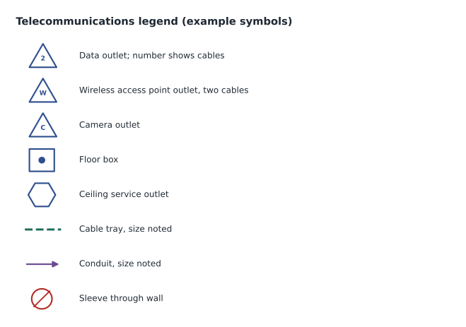
Lakehead Signal's legend uses a triangle for outlets, with a number inside showing how many cables serve it and a letter showing its type, such as W for a wireless access point and C for a camera. Each outlet also carries a tag that links it to the outlet schedule, so the drawing itself shows location and count while the schedule shows the details. Daniel's mistake on his first legend was to use two slightly different triangles for the same thing on different floors because he had copied symbols from two older projects. Tomasz spotted it in five minutes.
Plans, scales and layering
Floor plans show outlets and pathways over a lightened background of the architect's floor plan. The background should show walls, doors, room names and numbers, and ceiling grids where they matter, but be faded so that the telecommunications information stands out. Most drawing software organizes information in layers, and a good layer scheme separates outlets, pathways, tags, notes and backgrounds so that each can be turned on or off or changed in weight.
Scale must suit the density of information. A floor plan of a large building is often drawn at a small scale, which keeps the whole floor on one sheet but can crowd outlet tags. Enlarged plans of telecommunications rooms are usually drawn at a much larger scale, because racks, clearances and wall fields must be shown accurately. Every plan should show a scale bar as well as a stated scale, because drawings are often printed at different sizes.
Drawing for the reader
Every drawing has several readers, and each looks for different things. The estimator counts symbols and measures routes. The installer looks for locations, mounting heights and details. The inspector looks for firestops, bonding and separation from power. The owner's technician, years later, looks for identifiers. A good drawing serves all of them without forcing any of them to search. Daniel learns to check each sheet by reading it as each of these people would: can the estimator count the outlets, can the installer find the mounting height, can the inspector see every penetration, can the technician find the identifier.
Consistency across sheets helps every reader. The same element should be shown the same way at the same line weight on every plan, the same notes should appear in the same place on each sheet, and the north arrow, scale bar and key plan should sit in the same corner. Small inconsistencies make readers doubt what they see, and doubt leads to RFIs.
Mounting heights and dimensions
Floor plans show where outlets are in plan, but not how high. Mounting heights are usually given in a general note or a detail, with exceptions tagged on the plans: outlets above counters, wall-mounted displays, access point outlets in high ceilings, and outlets for wall phones. Accessibility rules set limits for outlets and controls that occupants must reach, and the designer must check them. Where an exact location matters, such as an outlet behind a wall-mounted display or a floor box under a reception desk, the plan should dimension it from a fixed reference such as a wall or column, because a symbol alone cannot show its position accurately enough.
Dimensions on telecommunications drawings should come from the same references the architect uses, such as column grid lines or finished wall faces, so that every trade measures from the same place. A dimension taken from a wall that later moves is a dimension that will be wrong when the work is built.
Worked problem
Measuring from a scale
On a floor plan drawn at a scale of 1 to 100, a cable tray route measures 386 millimetres on the sheet. How long is the tray in the building?
Show solution
- At 1 to 100, each millimetre on the drawing is 100 millimetres in the building.
- 386 × 100 = 38,600 millimetres.
- 38,600 millimetres = 38.6 metres.
Answer: The tray is 38.6 metres long. If the sheet was printed at half size, the same route would measure 193 millimetres, which is why a scale bar matters.
Worked problem
Checking a room plan
An enlarged plan of a telecommunications room is drawn at 1 to 25. The room measures 120 millimetres by 160 millimetres on the sheet. What are its real dimensions and floor area?
Show solution
- Width: 120 × 25 = 3,000 millimetres = 3.0 metres.
- Length: 160 × 25 = 4,000 millimetres = 4.0 metres.
- Area: 3.0 × 4.0 = 12.0 square metres.
Answer: The room is 3.0 by 4.0 metres, or 12 square metres.
Elevations and diagrams
Rack and cabinet elevations show the front of each rack with every item in its rack unit: patch panels, cable managers, fibre enclosures, switches, power distribution units and blank panels. They let the contractor build the rack exactly as designed, and they let the owner see how much space remains. A good elevation labels each item with its identifier and type, shows the rack's identifier and grid position, and includes notes on cable entry, bonding and power.
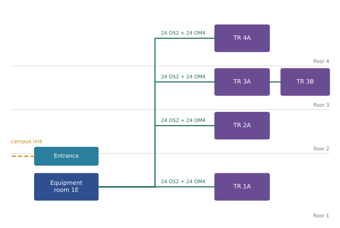
Riser diagrams show the backbone as a schematic: telecommunications spaces stacked by floor, with lines between them for each backbone cable, labelled with its type, count and identifier. They are not drawn to scale; their job is to show what connects to what. Bonding diagrams do the same for the bonding infrastructure, showing the primary busbar, each secondary busbar, the bonding backbone and the connections to building steel and electrical grounding. Campus diagrams show outside plant between buildings.
Details and notes
Typical details show how recurring items are installed: an outlet box and its conduit stub, a floor box, a sleeve through a fire-rated wall with its firestop, a cable tray bonding jumper, a rack anchor. Details save the contractor from guessing and save the designer from repeating the same information on every plan. Each detail should be referenced from the plans with a callout, so that a reader at a particular wall knows which detail applies.
Notes come in two kinds. General notes apply to the whole set and usually sit on the first sheet. Keyed notes apply to specific locations and are referenced by a number or symbol on the plan. Notes should be short, specific and consistent with the specifications. A note that says install per manufacturer's instructions adds nothing; a note that says route cables above the corridor ceiling in tray, see detail 3 on sheet T5.01 tells the contractor exactly what to do.
Coordination with other disciplines
Telecommunications drawings must agree with the architect's, the electrical engineer's and the mechanical engineer's drawings. Cable tray must not run through ducts. Telecommunications rooms must not have water pipes crossing them. Every outlet that needs power must have a power outlet beside it on the electrical drawings, and every rack that needs a circuit must have one. Many projects now coordinate in a shared building information model, where clashes between trays, ducts, pipes and structure can be found automatically. On projects without a model, the designer overlays drawings and walks them line by line.
Daniel's clash review for Harbourview found the problem that RCDD-110 described: a feeder cable route on the electrical drawings ran alongside the main third-floor tray. The fix, moving the tray and crossing the feeder at right angles, was made on both disciplines' drawings in the same revision, which is the only way to make sure a fix sticks.
Revisions
Drawings change during design and construction, and every change must be controlled. Each revised sheet gets a new revision number or letter, a date and a short description in the title block's revision history, and the changed area is marked with a revision cloud and a delta symbol carrying the revision number. A revision issued during construction, often through an addendum during bidding or a change notice during construction, goes to everyone who holds the set. Superseded sheets must be withdrawn or clearly marked so that nobody builds from an old revision.
Common mistakes
MistakeUsing a symbol that is not in the legend.
InsteadDefine every symbol, and use the same symbol for the same thing everywhere.
MistakeRepeating specification text in drawing notes.
InsteadRefer to the specification instead of restating it.
MistakeShowing only a stated scale.
InsteadShow a scale bar so drawings can be measured at any print size.
MistakeFixing a clash on one discipline's drawings only.
InsteadRevise every affected discipline's drawings together.
MistakeIssuing a changed sheet without marking the change.
InsteadCloud the change, add a delta and update the revision history.
Summary and key terms
- Drawings show where things go and how much there is; specifications describe what they are and how to install them.
- Sets are organized by discipline and sheet type: general, site, plans, enlarged plans, elevations, diagrams, details and schedules.
- Every symbol must be defined in the legend and used consistently.
- Scale must suit the density of information, and a scale bar lets drawings be measured at any size.
- Elevations, riser diagrams, bonding diagrams and details each show a different aspect of the design.
- Drawings must be coordinated with other disciplines and revised under control.
- Legend
- The sheet or table defining every symbol and abbreviation used.
- Title block
- The area of a sheet with the project, sheet title, number, scale and revisions.
- Enlarged plan
- A larger-scale plan of a dense area such as a telecommunications room.
- Elevation
- A drawing of a vertical face, such as the front of a rack.
- Keyed note
- A note referenced from a specific location on a drawing.
- Revision cloud
- A scalloped outline marking a changed area on a revised drawing.
Practice problems
Work each problem on paper first, then reveal the answer to check.
What letter prefix is commonly used for telecommunications sheets?
Show answer
T.
A route measures 250 mm on a 1 to 200 drawing. How long is it?
Show answer
50 m.
Why should a riser diagram not be drawn to scale?
Show answer
Its job is to show connections, not distances.
What should happen to superseded sheets?
Show answer
They should be withdrawn or clearly marked.
What makes a drawing note useful?
Show answer
It is short, specific and tells the reader exactly what to do.
How are clashes found on projects with a building model?
Show answer
By automatic clash detection in the model.
Lesson quiz · 5 questions
Score 60% or more to complete this lesson.
Create a free account to save your progress, take quizzes and earn a certificate.