
RCDD-116 · Lesson 5 of 12 · 23 min
Documentation and record drawings
▶ Video coming soon A video version of this lesson is on the way.
A year after Harbourview opens, the college decides to turn two third-floor classrooms into a simulation suite. The architect calls Lakehead Signal to ask what cabling is in the ceiling, which telecommunications room serves those rooms, how much space is left in the tray and how many spare ports remain on the panels. Daniel answers every question in twenty minutes from the closeout documents, without leaving the office. Roz tells him that this phone call is the real test of a design: not whether the building works on opening day, but whether the next person can understand it.
Why documentation matters
Telecommunications infrastructure outlives the people who design and install it. The cabling in a new building may serve for twenty years or more, through several generations of network equipment, dozens of renovations and many changes of staff. Every one of those changes depends on knowing what is already there. Without documentation, each change starts with investigation: tracing cables, opening ceilings, counting ports. With good documentation, it starts with a drawing and a database query.
Documentation also has legal and contractual weight. Record drawings and test results prove what was delivered under the contract. They support warranty claims years later. They show inspectors and insurers that firestopping, bonding and separation from power were done as required. And they protect the designer, who may one day need to show what was specified and what was approved.
The documentation set
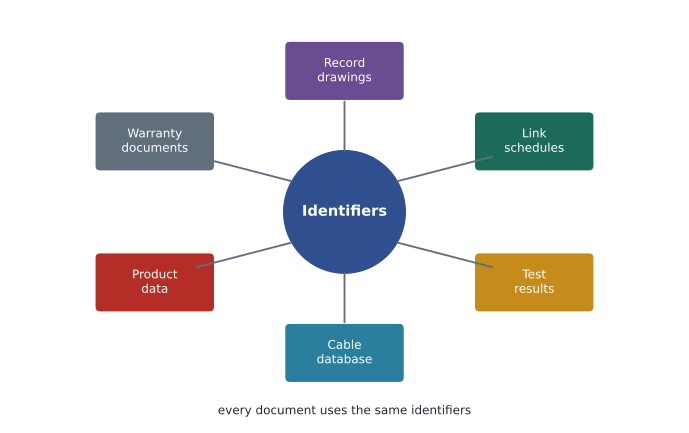
A complete documentation package for structured cabling has several parts that work together. Each refers to the same identifiers, so that an element can be found in any of them.
| Document | What it records |
|---|---|
| Record drawings | Floor plans with every outlet, pathway and space as installed; enlarged room plans; rack elevations; riser and campus diagrams. |
| Outlet and link schedule | Every link with its identifier, outlet location, panel port, cable type and length. |
| Backbone and campus schedules | Every backbone cable, its strands or pairs, and the positions where they terminate. |
| Test results | Native tester files and summaries for every copper link and fibre strand. |
| Cable database | The records required by the administration standard, linking every element to its connections. |
| Product data and submittals | Approved product data sheets, shop drawings and samples. |
| Warranty documents | Manufacturer certificates, the warranty schedule and registration details. |
| Operations information | The identifier scheme, labelling rules, maintenance guidance and spare stock lists. |
Design drawings, shop drawings and record drawings
Three kinds of drawings appear over the life of a project, and they serve different purposes. Design drawings, issued by the designer as part of the construction documents, show the intended design: outlet locations, pathway routes, room layouts and details. Shop drawings, prepared by the contractor and reviewed by the designer, show how the contractor proposes to build parts of the work, such as rack layouts with actual equipment, cable tray routes coordinated with other trades, or custom fabrications. Record drawings show what was actually built.
The terms record drawings and as-built drawings are often used loosely and interchangeably, but many designers and contracts distinguish them. As-built drawings are usually the contractor's marked-up set, kept on site throughout construction and updated with every deviation from the design: an outlet moved, a pathway rerouted, a sleeve added. Record drawings are the clean, final set prepared from those markups, usually by the designer or under the designer's direction, and issued at closeout. The specification should say who prepares each, in what format, and when.
Keeping as-builts current during construction is the only reliable way to get accurate record drawings. Changes made in the field and recorded months later are recorded badly or not at all. Daniel's specification requires the contractor to keep a marked-up set in the site office and to update it at least weekly, and Daniel checks it at each site visit. When the contractor moves a classroom outlet to clear a whiteboard, the markup shows the new location the same week.
What record drawings show
Record drawings for structured cabling usually include the following sheets. They follow the same sheet organization as the design drawings, covered in lesson 8, so that a reader who knows one set can find their way around the other.
- A legend and general notes, listing symbols, abbreviations and the identifier scheme.
- Floor plans showing every outlet with its identifier, every pathway with its size and route, and every telecommunications space.
- Enlarged plans of each telecommunications space, with racks, cabinets, wall fields and clearances.
- Rack and cabinet elevations, showing every panel, manager and piece of equipment in its rack unit.
- Riser diagrams for the backbone, showing every cable with its type and strand or pair count.
- Campus and outside plant drawings with duct banks, maintenance holes and building entrances.
- Bonding diagrams showing busbars, bonding conductors and their connections.
Each outlet on the floor plans should carry its full identifier, or at least the part that is unique on that sheet with the rest given in a note. Drawing scale matters: a floor plan crowded with 600 identifiers may need to be split into zones or shown at a larger scale so that every label is legible when printed.
Schedules and the cable database
Drawings show where things are. Schedules and the database show what they are and how they connect. The outlet and link schedule that started as a design tool, described in RCDD-112, becomes a record when it is updated with the as-built information: the actual panel port of each link, its measured length from the test results, and any changes. The backbone schedules record which strand or pair is in which position at each end, and which are in use.
The cable database brings these together. In a simple form it is a set of linked tables in a spreadsheet: spaces, racks, panels, ports, links and cables, each with its identifier and its relationships. In a fuller form it is dedicated infrastructure management software that can show a circuit from switch port to outlet, track changes and produce reports. Data centres often use data centre infrastructure management software that also tracks power, cooling and equipment. The designer should specify the format of the database deliverable, including field names, so that it can be loaded into whatever system the owner uses.
Who owns the documentation
Documentation raises questions of ownership and use that are worth settling in the contracts. The designer usually holds copyright in the drawings and specifications, while the owner receives the right to use them to build, operate and maintain the building. Record drawings and the cable database are delivered to the owner for that purpose. The owner may also want the right to give them to future designers and contractors, which is normal, and the design services agreement should say so. Product data and test results belong to the project record, and the manufacturer warranty usually requires the owner to keep the test results for the life of the warranty.
Security is a second concern. Detailed drawings of telecommunications rooms, security cabling and outside plant routes can help someone who wants to disrupt a building. Many owners, especially in health care, government and critical infrastructure, classify these documents and control who receives them. The specification can require that documentation be delivered through a secure file transfer, that paper copies be numbered and tracked, and that the contractor return or destroy working copies at closeout.
Documentation during the design phases
Documentation starts long before construction. Each design phase produces its own records: the needs analysis notes and basis of design, progress sets and their review comments, coordination meeting minutes, and the design narrative that explains why key decisions were made. These records are not delivered to the contractor, but they matter. When a future renovation asks why a telecommunications room is where it is, or why the backbone has a particular strand count, the design narrative answers it. Roz insists that every project at Lakehead Signal ends with a short design narrative filed alongside the record drawings, so that the reasoning survives as well as the result.
The design narrative for Harbourview runs to eleven pages. It records the owner's requirements, the choice of Category 6A and a single warranted system, the reasons for two diverse backbone routes to the clinic floors, the decision to cable wireless on a grid, the screened cabling in the imaging room, and the value engineering decisions with the owner's choices. It also lists the assumptions that future designers should check, such as the expected growth in Power over Ethernet devices.
Worked problem
Estimating drawing sheets
Each Harbourview floor plan for cabling is drawn at a scale that fits about 160 legible outlet identifiers per sheet. The four floors have 386, 412, 570 and 44 links. How many floor plan sheets are needed if each floor is split into zones with whole sheets?
Show solution
- Floor 1: 44 / 160 = 0.3, so 1 sheet.
- Floor 2: 386 / 160 = 2.4, so 3 sheets.
- Floor 3: 570 / 160 = 3.6, so 4 sheets.
- Floor 4: 412 / 160 = 2.6, so 3 sheets.
- Total: 1 + 3 + 4 + 3 = 11 sheets.
Answer: Eleven floor plan sheets, plus the enlarged room plans, elevations and diagrams.
Formats and file delivery
Documentation that cannot be opened is documentation that does not exist. Drawings should be delivered both in the native design format, so that they can be edited, and as PDF files, so that anyone can read them. Building information modelling, or BIM, is increasingly common, and an owner who uses a building model may want the cabling, pathways and spaces modelled in it with their identifiers as properties. Test results should be delivered in the tester's native format and as PDF summaries. The database should be delivered in an open, editable format such as a spreadsheet or comma-separated files, even if it was built in proprietary software.
File naming and organization matter on a large project. A set of a few thousand files with names like test1 and drawing-final-final helps no one. The specification can require a folder structure and naming convention, such as project, discipline, sheet number and revision for drawings, and the link identifier for each test result.
Reviewing documentation at closeout
The designer reviews the documentation before recommending final acceptance, just as the designer reviews test results. Daniel's checklist compares the record drawings with the database and the test results by sampling: he picks thirty identifiers at random and checks that each appears on a drawing, in the database and in the test results, with the same location and the same panel port. He also checks that every change order and every field change recorded during construction appears on the record drawings.
Worked problem
Sampling documentation
Daniel samples 30 links from the third floor. Two are missing from the record drawings and one has a different panel port in the database than in the test result. What share of the sample has a problem, and what should happen next?
Show solution
- Problems: 2 + 1 = 3 links.
- Share: 3 / 30 = 0.10, or one in ten.
- One in ten is too high to accept; the contractor should check the whole floor, not just the three links.
Answer: One in ten links sampled has a problem, so the documentation for the floor is returned for a full review.
Documentation over the life of the building
Documentation is only valuable if it stays current. After handover, the owner becomes responsible for updating it with every move, addition and change. The designer can make that easier by delivering editable files, writing clear notes on the identifier scheme and the drawing conventions, and recommending a process for updates. Ines plans to require that every project in the building, however small, delivers updated drawings and database records as a condition of payment, and to review them herself before closing each work order.
Common mistakes
MistakeProducing record drawings from memory at the end of the job.
InsteadKeep as-built markups current during construction and prepare records from them.
MistakeDelivering drawings only as PDF files.
InsteadDeliver native files for editing and PDF files for reading.
MistakeUsing different identifiers in drawings, schedules and the database.
InsteadUse the same identifiers everywhere.
MistakeCrowding a floor plan until labels are illegible.
InsteadSplit the floor into zones or enlarge the scale.
MistakeAccepting documentation without checking it.
InsteadSample identifiers across drawings, database and test results before acceptance.
Summary and key terms
- Documentation lets the next person understand and change the infrastructure without investigation.
- The documentation set includes record drawings, schedules, test results, the cable database, product data, warranties and operations information.
- Design drawings show intent, shop drawings show the contractor's proposal and record drawings show what was built.
- As-built markups must be kept current during construction to produce accurate records.
- Deliver native and PDF drawings, native and summary test results, and an editable database.
- Review documentation by sampling identifiers across all documents before acceptance.
- Record drawings
- The final drawings showing what was installed, issued at closeout.
- As-built drawings
- The contractor's marked-up drawings kept current during construction.
- Shop drawings
- Drawings prepared by the contractor showing how part of the work will be built.
- Rack elevation
- A drawing of the front of a rack showing every item in its rack unit.
- Riser diagram
- A schematic drawing of the backbone cabling between spaces.
- BIM
- Building information modelling, a shared digital model of the building and its systems.
Practice problems
Work each problem on paper first, then reveal the answer to check.
What is the difference between as-built and record drawings?
Show answer
As-builts are the contractor's field markups; record drawings are the clean final set prepared from them.
A floor has 500 links and a sheet fits 150 legible identifiers. How many sheets?
Show answer
4.
Why deliver drawings in native format?
Show answer
So they can be edited and kept current.
What should every document in the set share?
Show answer
The same identifiers.
A sample of 40 finds 2 problems. What share is that?
Show answer
1 in 20.
Who keeps documentation current after handover?
Show answer
The owner, with every move, addition and change.
Lesson quiz · 5 questions
Score 60% or more to complete this lesson.
Create a free account to save your progress, take quizzes and earn a certificate.