
RCDD-116 · Lesson 2 of 12 · 24 min
Fibre testing: loss and OTDR
▶ Video coming soon A video version of this lesson is on the way.
The fibre backbone at Harbourview is small next to the copper: twenty-four OS2 singlemode and twenty-four OM4 multimode strands to each telecommunications room, and a 410-metre singlemode link across the campus to the existing building. But every network switch in the building depends on it. When the contractor's first fibre test report arrives, Daniel notices that every multimode link shows a loss of exactly 0.00 dB at 850 nanometres. Roz looks over his shoulder and says the report proves only one thing: that somebody set the reference wrong. This lesson explains why, and how optical links should be tested.
Two tiers of fibre testing
ANSI/TIA-568.3 and the IEC 61280 and IEC 14763-3 documents describe two levels of field testing for installed optical fibre. Tier 1, sometimes called basic testing, measures the attenuation, or insertion loss, of each link with a light source and power meter, confirms the length and checks polarity, which means that the transmit fibre at one end arrives at the receive position at the other. Tier 1 is required for acceptance. Tier 2, sometimes called extended testing, adds an optical time domain reflectometer trace of each fibre. It shows where the loss occurs: at each connector, splice, bend or break along the link. Tier 2 is optional in the standards but commonly required for backbones, campus links and data centres, and many manufacturer warranties ask for it.
The two tiers answer different questions. Tier 1 tells you whether the link meets its loss budget, which is the number that decides whether the network will work. Tier 2 tells you why a link has the loss it has, which is what you need to find a bad splice, prove the workmanship of each connection, or build a baseline for future troubleshooting. Neither replaces the other: an OTDR is not accurate enough to measure total link loss for acceptance, and a power meter cannot see where the loss is.
Loss testing with a light source and power meter
An optical loss test set, or OLTS, has a light source at one end and a power meter at the other. The technician first sets a reference by measuring the power through a test cord alone, then connects the link and measures again. The difference is the loss of the link. Multimode links are tested at 850 and 1300 nanometres, and singlemode links at 1310 and 1550 nanometres, because loss varies with wavelength and different applications use different wavelengths. Links are usually tested in both directions as well, because some connections lose slightly more light in one direction than the other.
How the reference is set decides what the measurement includes. With the one-cord reference method that TIA recommends for most installed links, the reference is set with one test cord between source and meter. The link is then connected with a second test cord at the far end, so the measurement includes the connections at both ends of the link plus everything in between. Two-cord and three-cord reference methods include fewer connections in the result and therefore show less loss. They exist for cases where the tester's ports do not match the link's connectors, but the report must say which method was used, and the loss budget must be calculated on the same basis.
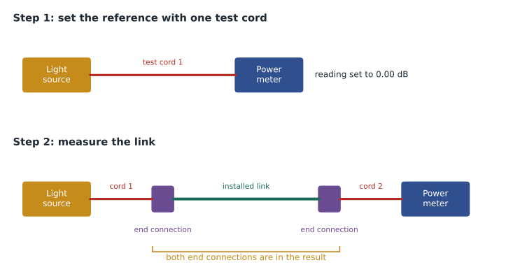
The 0.00 dB results in Harbourview's first report came from a technician who set the reference through the link itself, or through a patch panel, rather than through a test cord alone. Every later measurement then subtracted the link's own loss from itself. A zero or negative loss on an installed link is physically impossible and always signals a reference problem. Roz has the contractor re-reference and retest the whole batch.
Launch conditions for multimode
Multimode loss measurements depend on how the light source fills the fibre's core. A source that overfills the core sends some light into high-order modes that are lost quickly at the first connections, so it shows more loss than the link will have in service. A source that underfills the core shows less. To make measurements repeatable, current standards specify an encircled flux launch condition for multimode testing, defined in IEC 61280-4-1 and adopted by TIA. In practice, the technician uses a source and test cord, or a launch controller, that the manufacturer certifies as meeting encircled flux. The specification should require it.
Test cords matter too. Reference-grade test cords have connectors with tightly controlled loss, so that the test cords themselves do not distort the result. They must be kept clean, inspected and replaced when worn. A scratched or dirty test cord can add tenths of a decibel to every measurement on a project.
Inspect and clean before you connect
Contamination is the most common cause of optical loss and failure. A single particle of dust on a connector end face can block light, and when two dirty connectors are mated the dirt can be pressed into the glass and damage both. IEC 61300-3-35 sets pass and fail criteria for end-face condition by zones of the end face. The working rule on site is simple: inspect every connector with a fibre microscope before mating it, clean it if it is dirty, and inspect it again. Many test specifications now require saved end-face images along with the loss results.
Calculating the loss budget
The test limit for each link is its calculated loss budget, built from the maximum component values in ANSI/TIA-568.3: about 0.75 dB per mated connector pair, 0.3 dB per splice, and a fibre attenuation of 3.5 dB per kilometre for multimode at 850 nanometres, 1.5 dB per kilometre at 1300, and 1.0 or 0.5 dB per kilometre for singlemode inside plant and outside plant. These are maximum allowances, not typical values; good installations usually measure well below them.
Here n_c is the number of mated connector pairs, n_s the number of splices, L the length in kilometres and α the fibre attenuation in dB per kilometre at the test wavelength. With a one-cord reference, the connections at both ends of the link count as mated pairs.
Worked problem
Loss budget for a riser link
A multimode OM4 riser link at Harbourview is 62 metres long, with a connector pair at each end and no splices. What is the maximum allowable loss at 850 nm?
Show solution
- Connectors: 2 × 0.75 = 1.50 dB.
- Fibre: 0.062 km × 3.5 dB/km = 0.217 dB.
- Total: 1.50 + 0.217 = 1.717 dB, rounded to 1.72 dB.
Answer: The limit is about 1.72 dB. A measured loss of 0.6 dB passes with more than 1 dB of margin.
Worked problem
Pass or fail on the campus link
The 410-metre singlemode campus link has a connector pair at each end and a splice at each building entrance. The contractor measures 1.31 dB at 1310 nm. Does it pass, using 0.5 dB/km for outside plant fibre?
Show solution
- Connectors: 2 × 0.75 = 1.50 dB.
- Splices: 2 × 0.3 = 0.60 dB.
- Fibre: 0.41 km × 0.5 dB/km = 0.205 dB.
- Budget: 1.50 + 0.60 + 0.205 = 2.305 dB.
- Margin: 2.305 − 1.31 = 0.995 dB.
Answer: It passes with almost 1 dB of margin.
The component budget is the acceptance limit for the cabling. It is not the same as the application's limit. A network application such as 10 gigabit or 100 gigabit Ethernet has its own maximum channel loss, which may be tighter than the component budget for a long or complicated link. The designer checks both at design time, as RCDD-112 showed, and the test report should show both so the owner can see which applications each link will support.
How an OTDR works
An optical time domain reflectometer sends short pulses of light into one end of a fibre and measures the light that comes back. A small amount of light is scattered back continuously along the glass, a process called backscatter, and much more is reflected at connectors and breaks. By timing the returns, the OTDR plots the power coming back against distance. The result, the trace, slopes gently down as the fibre attenuates the light, with steps at splices and connectors and spikes at reflective events.
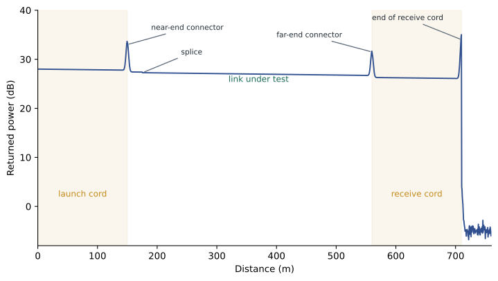
Reading a trace takes practice. Each event has a location, a loss and, for reflective events, a reflectance. A fusion splice usually appears as a small, non-reflective step. A mated connector appears as a reflective spike followed by a step. The end of the fibre appears as a large reflection followed by noise. Loss between events is the fibre's attenuation over that distance. Modern OTDRs analyse the trace automatically and list each event with pass or fail against limits the user sets, but the technician should still look at the trace, because automatic analysis can miss or misread events.
Launch and receive cords, dead zones and gainers
Right after a strong reflection, the OTDR's detector is briefly blinded and cannot see events close behind it. That distance is the dead zone, and it is why the first connector of a link cannot be measured if the OTDR is plugged straight into it. The fix is a launch cord, also called a launch fibre, at least as long as the dead zone and often 100 to 300 metres or more, placed between the OTDR and the link. A receive cord at the far end does the same for the last connector. Without both cords, the end connectors, which are the ones most often damaged, are not measured at all.
OTDRs measure loss from backscatter, and backscatter differs slightly between fibres. When two fibres with different backscatter coefficients are spliced, the trace can show a splice with apparent gain in one direction, a gainer, and exaggerated loss in the other. That is why accurate splice loss requires testing from both ends and averaging the two results. Bidirectional OTDR testing is standard practice for outside plant and for any link where splice quality is under question.
Worked problem
Bidirectional splice loss
An OTDR test of a splice shows a loss of 0.41 dB from end A and a gain of 0.17 dB, recorded as −0.17 dB, from end B. What is the true splice loss?
Show solution
- Average the two directions: (0.41 + (−0.17)) / 2.
- = 0.24 / 2 = 0.12 dB.
Answer: The splice loss is about 0.12 dB, well within a 0.3 dB allowance, even though the one-direction result of 0.41 dB looked like a failure.
What the fibre test report should contain
For each fibre, a complete Tier 1 report gives the link identifier, the reference method, the wavelengths, the loss in each direction, the calculated limit and margin, the length and the polarity result, plus the tester, its calibration and the test cord details. A Tier 2 report adds the OTDR trace files, the event table and the launch and receive cord lengths. End-face inspection images, where specified, are filed with the same identifiers. Daniel's specification requires all of these, in native tester files and in a summary, and requires the reference method to be printed on every page so that a result like 0.00 dB can be caught immediately.
Common mistakes
MistakeAccepting zero or negative loss results.
InsteadA zero or negative loss always means the reference was set wrong; retest.
MistakeUsing an OTDR result as the acceptance loss.
InsteadAccept links on light source and power meter loss; use the OTDR to locate and characterize events.
MistakeTesting without launch and receive cords.
InsteadUse cords longer than the dead zone at both ends so the end connectors are measured.
MistakeJudging splice loss from one direction.
InsteadTest from both ends and average to remove gainers and exaggerated losses.
MistakeConnecting before inspecting.
InsteadInspect, clean if needed and inspect again before every mating.
Summary and key terms
- Tier 1 testing measures loss, length and polarity with a light source and power meter and is required for acceptance.
- Tier 2 adds an OTDR trace that locates and measures each event along the fibre.
- The reference method decides which connections are included; the one-cord method includes both end connections.
- Multimode loss testing needs an encircled flux launch for repeatable results.
- Loss budgets use maximum component values: 0.75 dB per connector pair, 0.3 dB per splice, plus fibre attenuation by wavelength.
- OTDR testing needs launch and receive cords and bidirectional averaging for accurate splice loss.
- OLTS
- Optical loss test set: a light source and power meter.
- Encircled flux
- A defined multimode launch condition that makes loss tests repeatable.
- OTDR
- Optical time domain reflectometer, which maps events along a fibre from backscatter and reflections.
- Dead zone
- The distance after a reflection in which an OTDR cannot see events.
- Launch cord
- A length of fibre placed between the OTDR and the link so the first connector can be measured.
- Gainer
- An apparent gain at a splice caused by different backscatter in the two fibres.
Practice problems
Work each problem on paper first, then reveal the answer to check.
At which wavelengths is multimode fibre normally tested?
Show answer
850 and 1300 nm.
What does a measured loss of 0.00 dB on an installed link indicate?
Show answer
The reference was set incorrectly.
Calculate the budget for a 90 m OM4 link with two connector pairs at 850 nm.
Show answer
1.50 + 0.315 = about 1.82 dB.
Why does an OTDR need a launch cord?
Show answer
So the first connector lies beyond the dead zone and can be measured.
A splice reads 0.30 dB one way and 0.02 dB the other. What is the loss?
Show answer
0.16 dB.
Which document sets end-face inspection criteria?
Show answer
IEC 61300-3-35.
Lesson quiz · 5 questions
Score 60% or more to complete this lesson.
Create a free account to save your progress, take quizzes and earn a certificate.