
RCDD-115 · Lesson 7 of 12 · 23 min
Outside plant pathways: underground and direct buried
▶ Video coming soon A video version of this lesson is on the way.
The geotechnical report for the Harbourview site arrives on a Friday. Daniel skims it for the words he has learned to look for: fill, clay, rock, groundwater. The parking lot sits on old fill over clay, with bedrock about four metres down and the water table well below the depth of any trench. 'That's good news,' Roz says. 'No rock to blast, no water in the trench. Now the hard part is deciding exactly what goes in the ground, because once it is buried, nobody will ever see it again until something goes wrong.'
Underground pathways carry most campus backbones. They protect cables from weather, vehicles and vandals, they last for decades and, when they are built with spare ducts, they let the owner add or replace cables without digging again. This lesson covers the two main kinds of underground plant: conduit systems, including concrete-encased duct banks, and direct buried cable. It also covers how cables are pulled into ducts, because pulling forces often decide where maintenance holes and handholes must go.
Conduit systems and duct banks
An underground conduit system is a set of ducts buried between structures such as maintenance holes, handholes and building entrances. Cables are pulled into the ducts after construction. The ducts may be laid directly in a trench and backfilled, or they may be encased in concrete to form a duct bank, which protects them from crushing and from damage by later digging. Concrete encasement costs more but is common under roads, parking lots and other areas with heavy loads or a high chance of future excavation.
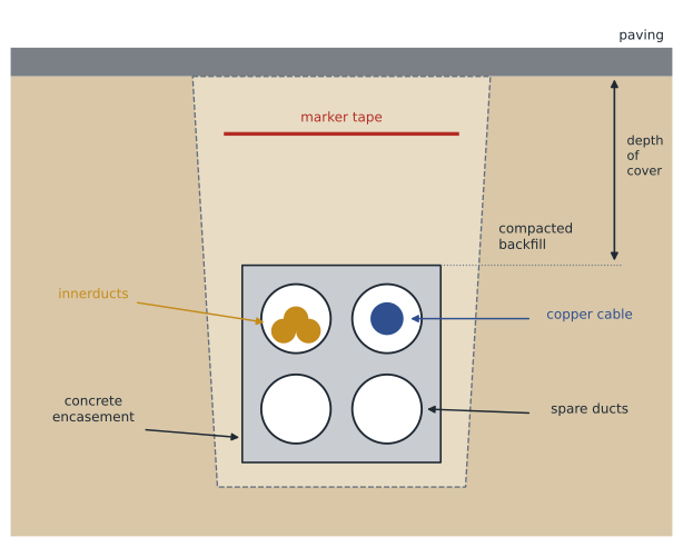
Ducts for telecommunications are typically 100 mm trade size, sometimes 50 or 75 mm for small branches. The most common materials are rigid PVC, either thick-walled for direct burial or thinner-walled types meant for concrete encasement, and high-density polyethylene, which comes in long coils and suits directional boring and plowing. Duct materials must be approved for the use under the standards adopted locally, such as the CSA standards for underground conduit, and joints must be glued or fused so that silt cannot enter.
A duct bank is designed as a cross-section. The designer chooses the number of ducts, their arrangement in rows and columns, the spacing between them, the thickness of concrete around them and the depth of cover from the top of the concrete to the finished grade. Typical designs place ducts in a grid held by plastic spacers every metre or two, with a few centimetres of concrete between ducts and at least 75 mm around the outside. The required depth of cover depends on the owner's standard, the road authority and the location, but cover of 600 to 900 mm to the top of the bank is common, with more under roads.
Worked problem
The Harbourview duct bank
Daniel must decide how many 100 mm ducts to put in the campus duct bank. Today the link needs one 144-fibre cable and the 25-pair copper cable. The college wants room for a second fibre cable within ten years and asks for spare capacity for the next thirty. How many ducts should he specify?
Show solution
- Today: one duct for the fibre cable, which will be pulled into an innerduct, and one for the copper cable.
- Planned second fibre cable: a second innerduct in the first duct, or another duct.
- Spares: owners commonly ask for at least one spare duct, and duct banks are cheapest to build with extra ducts at the start.
- A 2 by 2 arrangement of four ducts gives two in use and two spare, in a compact bank.
Answer: Four ducts in a 2 by 2 bank: one with three innerducts for fibre, one for the copper cable and two spares. The cost of extra ducts is small compared with the cost of the trench.
Innerduct
Pulling a single small fibre cable into a large duct wastes space, because a second cable pulled in later may wrap around and damage the first. Innerduct solves this. It is smaller, flexible plastic tubing, often corrugated or ribbed inside to reduce friction, pulled into the main duct before any cables. A 100 mm duct commonly holds three innerducts of about 32 mm, and each innerduct takes one fibre cable. Fabric innerduct, made of woven textile cells, packs even more cables into one duct. Each innerduct should have a pull line left in it for the next cable.
How full can a duct be?
Cables must fit loosely enough to be pulled without damage and, for heat-producing power cables, to dissipate heat. Telecommunications cables do not produce much heat, but friction and jamming still limit fill. The common guidance for three or more cables in a conduit, adopted from electrical practice, is to use no more than about four tenths of the conduit's internal area. For a single cable the practical limit is set by pulling tension and jamming rather than area.
Worked problem
Checking innerduct fill
Three innerducts, each with an outside diameter of 33 mm, are to be pulled into a duct with an inside diameter of 102 mm. What is the fill ratio, and is it within four tenths?
Show solution
- Sum of squared diameters: 3 × 33² = 3 × 1,089 = 3,267.
- Duct diameter squared: 102² = 10,404.
- Fill ratio: 3,267 ÷ 10,404 ≈ 0.31.
Answer: About 0.31, comfortably within the four tenths guidance. Check the innerduct maker's recommendations as well.
Pulling cables
Every cable has a maximum rated pulling tension, given by the manufacturer. Outside plant fibre cables commonly have ratings in the range of 2,700 newtons, but the actual value must come from the data sheet. If the force needed to pull a cable through a duct section exceeds the rating, the fibres can be strained, causing loss now or failure years later. Tension builds up along straight runs because of friction with the duct wall and multiplies at every bend, so long sections with many bends are the main risk.
In these formulas μ is the coefficient of friction between cable and duct, typically 0.2 to 0.5 depending on materials and lubricant, w is the cable's weight per metre in newtons, L is the length in metres and θ is the bend angle in radians. A 90 degree bend is π/2 or about 1.57 radians. The bend formula, often called the capstan equation, shows why bends matter: each one multiplies the tension rather than adding to it.
Worked problem
Tension through a section
A fibre cable weighing 0.20 kg per metre is pulled 120 m through a straight duct and then around one 90 degree sweep. The coefficient of friction is 0.3. Estimate the tension at the end of the section, ignoring the starting tension.
Show solution
- Weight per metre in newtons: 0.20 × 9.81 ≈ 1.96 N/m.
- Straight run: 0.3 × 1.96 × 120 ≈ 70.6 N.
- Bend multiplier: e^(0.3 × 1.57) = e^0.471 ≈ 1.60.
- After the bend: 70.6 × 1.60 ≈ 113 N.
Answer: About 113 N, far below a typical rating. Tension becomes a problem on long sections with several bends, or when a bend comes at the end of a long straight pull.
Because bends multiply tension, outside plant standards and owners limit the total bend between pull points. A common rule is no more than 180 degrees of bends, for example two 90 degree sweeps, in any section between maintenance holes, handholes or other pull points. Sweeps should have large radii, much larger than the minimum bend radius of the cable, which for fibre is typically twenty times its diameter while being pulled and ten times when installed. Pulls should use lubricant approved by the cable maker, a swivel between the pull rope and the cable, and a breakaway link or tension meter that stops the pull if the rated tension is reached.
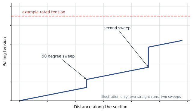
Pull direction matters too. Because bends multiply whatever tension already exists, pulling from the end nearest the bends usually needs less force than pulling from the far end. For very long runs, cable can be pulled from a midpoint in both directions, with the cable laid out in a figure eight on the ground so that it does not twist, or pulled by a blowing machine that uses air to carry the cable through the duct with very little tension.
Directional boring
Under the municipal street, the college does not want an open trench, and neither does the city. Horizontal directional drilling, often called directional boring, drills a pilot hole under the obstacle from a pit on one side, enlarges it and pulls a coil of polyethylene duct back through. It avoids cutting the road and disturbing traffic. The bore path must be planned around existing utilities, which must be located and, where they cross the bore, exposed by careful digging, as Lesson 12 explains. The depth under the road is set by the road authority's permit.
Direct buried cable
Direct buried cable is laid in the ground with no duct. It is cheaper to install than a conduit system, especially over long distances in open country where a plow can cut a slot and lay the cable in one pass. But it cannot be replaced or added to without digging again, and it is more exposed to damage by later digging or by rodents. Cables for direct burial are designed for it, usually with a metallic armour or a heavy jacket, and they must be laid at a depth required by the owner's standard and local rules, with a marker tape or warning ribbon above and, for dielectric cables, a tracer wire so that the cable can be found later.
On most campuses, direct buried cable is used only where future changes are unlikely and the route is easy to locate: a long run across a field to a remote building, for instance. Where the route crosses roads, parking lots or areas likely to be dug up later, conduit is the safer choice. Daniel considers direct burial for a future connection to the college's sports field lights but recommends a single duct with innerduct instead, because the field is due to be regraded in five years.
Separation from other utilities
Underground telecommunications plant must be kept apart from other utilities. Separation from power cables protects people working on either system and limits interference. Separation from gas, water and sewer lines protects all of them during repairs. The required distances come from the electrical and safety codes adopted locally, the overhead and underground systems standards in the CSA C22.3 series, utility standards and the owner's or road authority's rules. Where telecommunications and power share a trench by agreement, called joint trench construction, the agreement sets the separation and the order in which ducts are laid.
| Item | What the designer specifies | Where the values come from |
|---|---|---|
| Depth of cover | Minimum cover to top of duct bank or cable | Owner standard, road authority, applicable code |
| Separation from power | Minimum distance or barrier | Electrical and safety codes, utility standards |
| Separation from other utilities | Minimum distance, crossing angle | Municipal and utility standards |
| Marker tape and tracer wire | Type, depth and continuity | Owner standard, locate requirements |
| Backfill and restoration | Materials, compaction, paving | Civil engineer, municipal standard |
Working with the civil engineer
On most projects the ICT designer does not draw the trench details alone. A civil engineer designs grading, drainage, paving and the structural parts of maintenance holes, and the ICT designer provides the duct count, arrangement, sweep radii, pull points and cable requirements. The two must agree on the route, the depth, the crossings with storm sewers and water mains and the restoration. Daniel meets the civil engineer on site with the survey drawing. They move the duct bank half a metre north to clear a storm sewer manhole and add a low point drain in one maintenance hole, because water will find its way into any duct system eventually.
Common mistakes
MistakeBurying just enough ducts for today's cables.
InsteadAdd spare ducts. They cost little during construction and avoid a second trench later.
MistakePulling a new cable into a duct that already holds one without innerduct.
InsteadUse innerduct so that each cable has its own path and later pulls cannot damage earlier cables.
MistakeAllowing too many bends between pull points.
InsteadLimit bends, commonly to 180 degrees per section, and use large-radius sweeps.
MistakeForgetting a tracer for dielectric cable.
InsteadAll-dielectric cables cannot be found by locating equipment without a tracer wire or marker system.
Summary and key terms
- Underground conduit systems use ducts, often concrete-encased in duct banks, between maintenance holes, handholes and buildings.
- Typical ducts are 100 mm PVC or HDPE, with innerduct to give each fibre cable its own path.
- Fill guidance for several cables is about four tenths of the duct area; pulling tension often decides section lengths.
- Tension adds along straight runs and multiplies at bends; limit bends between pull points and pull from the end nearest the bends.
- Directional boring crosses roads without trenching; direct buried cable is cheaper but cannot be replaced without digging.
- Depth, separation, markers and restoration come from codes, utilities, road authorities and owner standards.
- Duct bank
- A group of underground ducts, often encased in concrete.
- Innerduct
- Small flexible tubing inside a duct that gives each cable a separate path.
- Pulling tension
- The force applied to a cable during installation, limited by the maker's rating.
- Capstan equation
- The relationship showing that tension multiplies by e to the power of friction times bend angle at each bend.
- Directional boring
- A trenchless method of installing duct by drilling a curved path under an obstacle.
- Tracer wire
- A conductor buried with dielectric cable so that the route can be located.
Practice problems
Work each problem on paper first, then reveal the answer to check.
Why place bends near the pulling end of a section?
Show answer
Bends multiply existing tension, so they add less force when the tension before them is low.
What is the bend multiplier for a 90 degree sweep with a friction coefficient of 0.4?
Show answer
e^(0.4 × 1.57) ≈ e^0.63 ≈ 1.87.
Give one reason to prefer conduit over direct burial on a campus.
Show answer
Cables can be added or replaced without digging, and the route is better protected.
Lesson quiz · 5 questions
Score 60% or more to complete this lesson.
Create a free account to save your progress, take quizzes and earn a certificate.