
RCDD-115 · Lesson 2 of 12 · 18 min
Data centre cabling topologies
▶ Video coming soon A video version of this lesson is on the way.
With the room chosen, Daniel turns to the cabling. Elena Varga sends over the college's plans: eight server and storage cabinets, two network cabinets and a pair of fabric switches that the network team calls 'the spine'. 'They want top-of-rack switches,' she writes, 'but our last consultant said that was wrong for a room this size. Can you settle it?' Roz laughs when Daniel shows her the email. 'There is no single right answer,' she says. 'There is a right answer for this room, this team and this budget. Your job is to lay out the options so they can choose with their eyes open.'
A topology is the arrangement of cabling between distribution points and equipment. In data centres, two related things are often called topology: the physical cabling structure, which is what TIA-942 describes, and the logical network architecture, which is what the network engineers design. They influence each other, and an RCDD needs to understand both well enough to support the network design with a cabling plant that will last longer than any one generation of switches.
The hierarchical star
The data centre cabling standard uses the same basic structure as building cabling: a hierarchical star. Backbone cables run from the main distribution area to each horizontal distribution area, and horizontal cables run from each HDA to the equipment cabinets in its zone. An optional zone distribution area may sit between the HDA and the equipment. Every channel has a predictable path, and the designer can trace any cabinet back to the core in no more than a few steps.
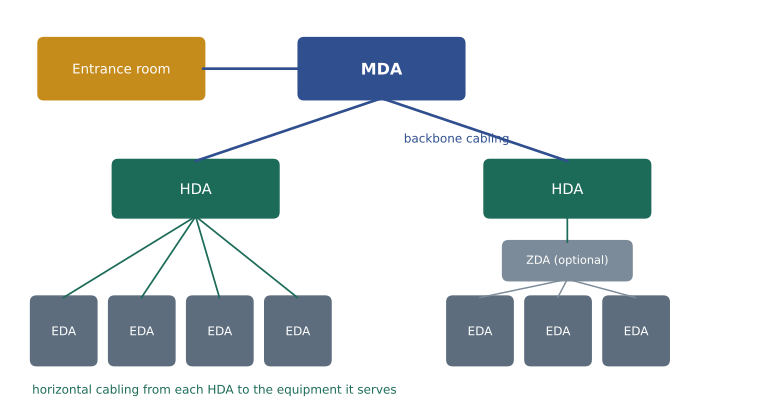
In a small data centre the hierarchy collapses. The MDA and HDA may be combined in one network row, and horizontal cables run directly from there to each equipment cabinet. TIA-942 calls this a reduced or collapsed topology. It is perfectly valid as long as the cabling still has a clear structure and the distances stay within limits. At Harbourview, with fewer than fifteen cabinets, Daniel expects a collapsed design: one network row holding the core switches and the combined main and horizontal cross-connect, with horizontal cables to each server cabinet.
Larger data centres may add a third level, an intermediate distribution area, between the MDA and several HDAs. Campus or multi-building data centres may also use distributed topologies where each building has its own MDA linked by campus backbone cables. The principle stays the same: a defined path from every piece of equipment to the core, with cross-connects at known points where changes can be made.
Where the switches go
The network team's question is not about the cabling standard at all. It is about where the access switches sit, the switches that servers connect to directly. Three arrangements are common, and each has different cabling consequences.
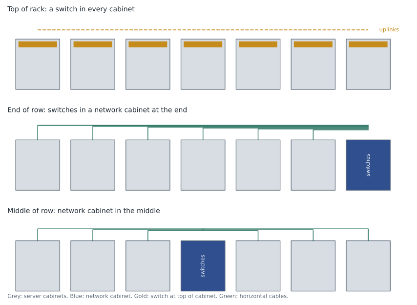
In a top-of-rack design, each equipment cabinet has one or two switches mounted at the top. Servers connect to them with short cords inside the cabinet, often direct attach copper cables or active optical cables of a few metres. Only uplinks leave the cabinet, usually on fibre to the aggregation or spine switches. Cabling between cabinets is minimal and server connections are short, which suits high port speeds where copper reach is limited. The drawbacks are that every cabinet needs switches whether it is full or not, that switch ports are often left unused, and that the network team has many more switches to manage.
In an end-of-row design, the access switches for a whole row sit in one or two network cabinets at the end of the row. Horizontal cables run from patch panels in each server cabinet to patch panels in the network cabinet, and patch cords there connect to the switches. Switch ports are used more efficiently and there are fewer switches to manage, but there is much more structured cabling, and the longest server channels may be 20 or 30 m, which affects which media can be used at high speeds.
Middle of row is the same idea with the network cabinet in the centre, which roughly halves the longest horizontal run. Some designers use pairs of network cabinets, one at each end, for redundancy, so that each server has a connection to two switches in different cabinets.
| Arrangement | Server connections | Structured cabling | Typical strengths | Typical drawbacks |
|---|---|---|---|---|
| Top of rack | Very short cords in the cabinet | Mostly fibre uplinks | Short reach suits high speeds; simple cabling | More switches; unused ports; switch refresh drives cabinet work |
| End of row | Horizontal cables to the row's network cabinet | Much copper or fibre per cabinet | Fewer switches; efficient port use | Longer channels; heavy pathways near the network cabinet |
| Middle of row | As end of row, shorter maximum | As end of row | Shorter longest run | Network cabinet interrupts the row |
Spine and leaf
Network engineers designing modern data centres usually use a spine-and-leaf architecture. Leaf switches are the access switches that servers connect to. Spine switches sit above them. Every leaf connects to every spine, so traffic between any two servers crosses at most one spine, and adding spines adds capacity without redesigning the network. The older three-tier design, with access, aggregation and core layers, sends traffic up and down a tree and can create bottlenecks for the server-to-server traffic that dominates modern applications.
For the cabling designer, spine and leaf has one clear consequence: a predictable but large number of links between leaf locations and spine locations. Each leaf has a fixed number of uplinks, and each uplink needs a fibre channel to a spine. If the leaves are top-of-rack switches spread through the room and the spines are in the network row, every cabinet needs fibre back to the network row. Counting those fibres correctly is the subject of the worked example below and of Lesson 5.
Worked problem
Counting spine-and-leaf fibre
Harbourview will have 10 leaf switches, one in each equipment cabinet, and 2 spine switches in the network row. Each leaf connects to each spine with one 100 gigabit link that uses a parallel optic interface needing 8 fibres. How many fibres must run between the cabinets and the network row, and how many should be installed if the owner wants one spare link for every leaf?
Show solution
- Links: 10 leaves × 2 spines = 20 links.
- Fibres in use: 20 × 8 = 160 fibres.
- With one spare link per leaf: 10 more links, or 80 more fibres.
- Total installed: 160 + 80 = 240 fibres, for example one 24-fibre trunk to each cabinet.
Answer: About 160 fibres in use and 240 installed. A 24-fibre trunk to each of the 10 cabinets gives exactly that, terminated on cassettes in the network row.
Cross-connect or interconnect?
At each distribution point, the designer chooses how equipment connects to the cabling. In an interconnect, equipment cords plug directly from the switch into the patch panel that terminates the horizontal or backbone cable. In a cross-connect, the switch ports are cabled permanently to a separate patch panel, and changes are made by moving patch cords between the equipment panel and the distribution panel. A cross-connect adds a connection to every channel, which costs insertion loss and money, but it means that nobody ever has to touch the cords plugged into an active switch to make a change. Many large data centres require a cross-connect at the MDA for exactly that reason.
The cost is real. Each additional mated pair in a high-speed multimode channel may use a quarter to three quarters of a decibel of a budget that may be under 2 dB in total, as RCDD-110 showed. A designer who specifies a cross-connect must check that the application will still work with the extra connection, often by specifying low-loss connectors.
Distances and media
Data centre channels are usually shorter than office channels, but the applications are faster, and faster applications often have shorter reach. Balanced twisted-pair cabling of Category 6A or better can support 10 gigabit Ethernet to 100 m, while Category 8 supports 25 and 40 gigabit Ethernet only to 30 m with no more than two connections, which suits top-of-rack and short end-of-row links. Above that, multimode and singlemode fibre carry most data centre traffic, with multimode reach falling as speed rises. Direct attach copper and active optical cables, which are factory-assembled with transceivers on each end, connect servers to switches within a cabinet or to the next cabinet but are not part of the structured cabling.
The cabling plan should state, for every link type, the media, the maximum length, the maximum number of connections and the applications it must support now and next. That table is what lets a future network team decide whether a new generation of switches can use the existing cabling.
| Link type at Harbourview | Media | Typical length | Notes |
|---|---|---|---|
| Leaf to spine | OM4 or singlemode fibre, MPO trunks | 5 to 20 m | Parallel optics today; plan for future duplex singlemode |
| Server to leaf, in cabinet | Direct attach cords | Under 3 m | Not structured cabling; owned by the network team |
| Management network | Category 6A to the network row | Up to 25 m | End-of-row management switches |
| Entrance room to MDA | Singlemode fibre, copper for provider services | About 15 m | Two diverse provider entrances |
Making the recommendation
Daniel's memo to Elena lays out the choices plainly. For a room of fourteen cabinet positions, a collapsed hierarchy with one network row is the right physical structure. For the access switches, top of rack fits the college's plan for high-speed servers and keeps copper runs short, but means twenty leaf switches if every cabinet gets two. End of row with a pair of network cabinets would use fewer switches but requires about 48 horizontal cables per server cabinet. Roz adds one sentence: 'Whichever you choose, we will install fibre trunks from every cabinet to the network row so that you can change your mind in five years without pulling new cable.' Elena chooses top of rack for compute and end of row for management, and the design proceeds.
Planning for change
Data centre networks change faster than buildings. A switch generation lasts perhaps five to seven years; the cabling plant should last fifteen or more. The cabling designer protects the owner by leaving room for change in three places. Pathways should have spare capacity, commonly enough to double the cables in each tray without exceeding its fill limit. Distribution areas should have spare rack space for more panels and cord management. And trunks should carry more fibres than today's switches need, in a connector base that suits more than one generation of optics. None of these costs much on the first day. Each one is expensive to add after the room is full of running equipment, when every change must be scheduled into a maintenance window and every new cable must be pulled through trays already crowded with live cords.
Common mistakes
MistakeAssuming top of rack means no structured cabling.
InsteadUplinks still need structured fibre to the spine or aggregation switches, and management networks often need copper.
MistakeAdding a cross-connect without checking the loss budget.
InsteadEach extra connection uses part of a tight high-speed budget. Check the channel and specify low-loss connectors if needed.
MistakeCounting fibres from today's switches only.
InsteadPlan fibre counts for spares and for likely future interfaces, which may use more or fewer fibres per link.
MistakeTreating direct attach cords as part of the permanent cabling.
InsteadThey are equipment cords, replaced with the equipment.
Summary and key terms
- Data centre cabling uses a hierarchical star from the MDA to HDAs to equipment, collapsing in small rooms.
- Access switches may be top of rack, end of row or middle of row, each with different cabling consequences.
- Spine-and-leaf networks connect every leaf to every spine, creating a predictable number of fibre links.
- Cross-connects make changes safer but add a connection to every channel; interconnects save loss and cost.
- Every link type needs defined media, length, connection count and supported applications.
- Hierarchical star
- A cabling structure in which each level connects to the level above at a single distribution point.
- Top of rack
- An arrangement with access switches in each equipment cabinet.
- End of row
- An arrangement with access switches for a whole row in network cabinets at the end of the row.
- Spine and leaf
- A network architecture in which every leaf switch connects to every spine switch.
- Cross-connect
- A distribution point where changes are made by patching between two sets of panels, without touching equipment cords.
- Interconnect
- A distribution point where equipment cords plug directly into the panel terminating the cabling.
Practice problems
Work each problem on paper first, then reveal the answer to check.
A site has 24 leaves and 4 spines, each link needing 2 fibres. How many fibres are in use?
Show answer
24 × 4 = 96 links; 96 × 2 = 192 fibres.
Why might a large data centre require a cross-connect at the MDA?
Show answer
So that changes are made by moving passive patch cords instead of handling cords in active core switches.
Which access switch arrangement gives the shortest server connections?
Show answer
Top of rack.
Lesson quiz · 5 questions
Score 60% or more to complete this lesson.
Create a free account to save your progress, take quizzes and earn a certificate.