
RCDD-115 · Lesson 4 of 12 · 22 min
Data centre power, cooling and availability tiers
▶ Video coming soon A video version of this lesson is on the way.
Elena Varga's next email is short. 'Our board wants to know how reliable the new room will be. Can you tell them it will be Tier III?' Daniel forwards it to Roz with a question mark. She calls him into her office. 'That word means something specific,' she says, 'and it is not ours to give away. What we can do is explain what reliability costs, what each level of redundancy buys and what the college actually needs. Then they can decide, and if they want a formal rating, they can pay someone to certify it.'
Data centre reliability depends on every system working together: the utility supply, the generators, the uninterruptible power supply, the power distribution to each cabinet, the cooling plant, the controls and the network itself. The cabling designer is not responsible for designing the power or cooling, but an RCDD must understand how they are arranged, because redundancy in power and cooling usually needs matching redundancy in cabling pathways, and because the language of availability ratings appears throughout data centre projects and on the exam.
From the utility to the cabinet
Power for a data centre follows a chain. The utility supplies the building's main electrical service. A standby generator, started automatically by a transfer switch, takes over when the utility fails. Because a generator takes several seconds to start and pick up load, an uninterruptible power supply, or UPS, sits between the building supply and the IT equipment. The UPS uses batteries, or sometimes a flywheel, to carry the load without interruption until the generator is ready. From the UPS, power flows through distribution panels or busway to power distribution units, and from there to rack power distribution units, the power strips inside each cabinet that the equipment plugs into.
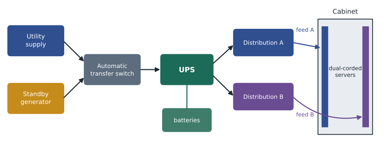
Most servers and network switches have two power supplies. If each is plugged into a different rack power strip, and each strip is fed from a different distribution path, the equipment keeps running when one path fails or is shut down for maintenance. These are called A and B feeds. The arrangement only works if both paths are truly separate all the way back to the UPS or beyond, and if each path is sized to carry the whole load on its own. A cabinet with two power strips fed from the same panel has only the appearance of redundancy.
Redundancy in plain words
Engineers describe redundancy with a simple notation based on N, the number of units needed to carry the load. A design with N units has no spare: if one fails, the load cannot be carried. N plus one has one spare unit. Two N has a complete second system, so either system can carry the whole load. Two N plus one adds a spare to each of two systems. The same notation applies to UPS modules, generators, cooling units, pumps and even network links.
| Arrangement | What it means | What it protects against |
|---|---|---|
| N | Just enough capacity for the load | Nothing beyond normal operation |
| N + 1 | One spare unit in a shared system | Failure or maintenance of any one unit |
| 2N | Two complete, independent systems | Failure or maintenance of a whole system, including its distribution |
| 2(N + 1) | Two independent systems, each with a spare | A system outage plus a unit failure in the other system |
N plus one protects against a failed module but not against a failure in the shared parts, such as a single output switchboard. Two N protects against almost any single failure because nothing is shared, but it doubles the equipment and leaves each system running at half load or less, which is less efficient. Designers choose between them by weighing the cost of downtime against the cost of the equipment.
Availability and downtime
Owners often ask for availability, the fraction of time a system is working. It is usually written as a decimal or as a number of nines: 0.999 is 'three nines' and 0.99999 is 'five nines'. The clearest way to explain availability to a board is to turn it into hours of downtime per year.
Worked problem
Explaining the nines
The college board asks what the difference is between availability of 0.999 and 0.9999. How many hours of downtime per year does each allow?
Show solution
- For 0.999: 8,760 × 0.001 = 8.76 hours per year.
- For 0.9999: 8,760 × 0.0001 = 0.876 hours, or about 53 minutes per year.
- Each extra nine cuts allowed downtime by a factor of ten.
Answer: About 8.8 hours per year for three nines and about 53 minutes for four nines. Getting from one to the other usually means adding redundancy in power, cooling and network paths.
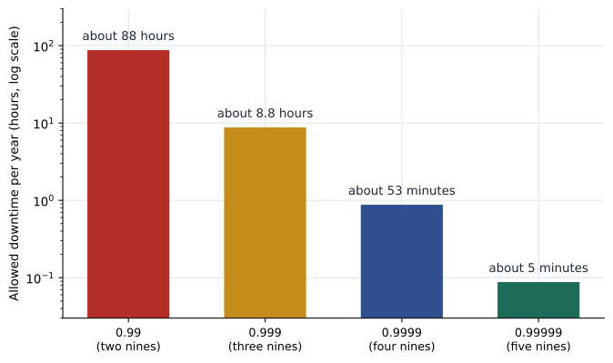
Availability figures are useful for comparing designs, but they are averages. A system with 53 minutes of expected downtime per year might have no outage for five years and then a four-hour outage. Owners should also ask how quickly a failure can be found and fixed, which depends on monitoring, spare parts and staff as much as on the design.
Tiers, ratings and classes
Several organizations publish frameworks that group data centre designs into levels of reliability. They use different names and different tests, and a designer must be careful to use the right one and not to claim a rating that has not been granted.
The Uptime Institute's Tier Classification System describes four tiers, written with Roman numerals. In general terms, Tier I is basic capacity with no redundancy; Tier II adds redundant capacity components; Tier III is concurrently maintainable, meaning any component or path can be taken out for planned maintenance without shutting down the IT load; and Tier IV is fault tolerant, meaning the site can withstand any single unplanned failure without affecting the IT load. The Tier names are owned by the Uptime Institute, and a site can only be described as Tier certified after the Institute has reviewed the design or the built facility.
ANSI/TIA-942 includes its own four rating levels, Rated 1 to Rated 4, covering telecommunications, architectural, electrical and mechanical systems, with conformity assessed by auditors under that standard's scheme. BICSI 002 uses availability classes, from Class F0 for a single path with no redundancy to Class F4 for the highest level, and links them to how critical the operation is and how much downtime it can tolerate. All three frameworks share the idea of increasing redundancy and maintainability, but their requirements differ in detail, so a design that meets one does not automatically meet another.
| Framework | Levels | Key idea at the higher levels |
|---|---|---|
| Uptime Institute Tier Classification | Tier I to Tier IV | Concurrent maintainability, then fault tolerance; certification by the Institute |
| ANSI/TIA-942 | Rated 1 to Rated 4 | Redundancy across telecommunications, architectural, electrical and mechanical systems |
| BICSI 002 | Class F0 to Class F4 | Availability class matched to the operation's tolerance for downtime |
What redundancy means for cabling
Power and cooling redundancy is wasted if the network has a single point of failure. A data centre with two UPS systems and one entrance conduit can be cut off by one excavator. As reliability goals rise, the cabling design must add matching redundancy: two entrance rooms or at least two entrance pathways from different directions; two separate campus or provider routes that never share a trench, maintenance hole or pole line; diverse backbone pathways from the entrance rooms to the MDA; and, at the highest levels, a second MDA. Network equipment then connects to both paths so that the loss of one does not stop traffic.
Pathway separation must be real. Two conduits in the same trench, or two cables in the same tray, are one pathway as far as an excavator or a fire is concerned. The design should show the routes on a site plan and state the minimum separation the owner requires, which may be several metres or more.
Cooling redundancy and efficiency
Cooling systems use the same notation. A room that needs three in-row cooling units to carry its load might have four installed, N plus one, so that any unit can fail or be serviced. Chilled water systems add redundancy in chillers, pumps and piping loops. Because cooling uses a large share of a data centre's energy, efficiency matters as much as redundancy. The common measure is power usage effectiveness, PUE, defined in ISO/IEC 30134-2 as total facility energy divided by IT equipment energy.
Worked problem
Estimating PUE
The Harbourview data room will have an IT load of 54 kW. The engineers estimate that cooling will use 16 kW, UPS and distribution losses 5 kW and lighting and other loads 2 kW. What is the expected PUE?
Show solution
- Total facility power: 54 + 16 + 5 + 2 = 77 kW.
- PUE: 77 ÷ 54 ≈ 1.43.
Answer: About 1.43. A perfect facility would have a PUE of 1.0, with all energy going to IT equipment.
Battery runtime
The UPS must carry the load until the generator takes over, or long enough for an orderly shutdown if there is no generator. A first estimate of the battery energy needed divides the load by the UPS efficiency and multiplies by the runtime. Battery makers' data sheets then give the actual capacity at that discharge rate and temperature, which is usually less than the nameplate because batteries deliver less energy at high discharge rates.
Worked problem
Sizing ride-through
The UPS must carry 54 kW for 10 minutes. The UPS inverter efficiency is 0.95. Roughly how much usable battery energy is needed?
Show solution
- Runtime: 10 minutes = 1/6 hour ≈ 0.167 h.
- Energy: 54 × 0.167 ÷ 0.95 ≈ 9.5 kWh.
Answer: About 9.5 kWh of usable energy at that discharge rate, before ageing and temperature allowances added by the electrical engineer.
Monitoring and emergency power off
Modern data centres are full of sensors: power meters in each distribution unit, temperature and humidity sensors on cabinets, leak detection under cooling units, door contacts and cameras. A data centre infrastructure management system collects them. The cabling designer must provide network connections for all of these, often on a separate management network. Some electrical codes and owners require an emergency power off control that disconnects power to IT equipment in an emergency; whether one is required, and how it must work, depends on the code adopted where the building is and on how the room is classified. The designer should confirm this with the electrical engineer and the authority having jurisdiction early, because an accidental emergency power off is itself a common cause of outages.
The recommendation to the board
Daniel's summary for the college board avoids the word Tier entirely. It describes a room with N plus one cooling, an N plus one UPS with batteries for ten minutes, a connection to the building's standby generator, dual A and B feeds to every cabinet and two separate network paths to the college: the underground campus link and a provider service entering from the street side. It explains how many hours of downtime per year each improvement is expected to remove and what each would cost. The board approves the design and decides not to seek a formal rating.
Common mistakes
MistakeAssuming two power strips mean redundant power.
InsteadEach strip must be fed from a separate path all the way back, and each path must carry the full load.
MistakeMatching power redundancy with a single network entrance.
InsteadProvide diverse entrances and routes so that one cut does not isolate the site.
MistakeUsing availability decimals without explaining them.
InsteadConvert to hours or minutes of downtime per year so owners understand what they are buying.
MistakeTreating tier, rating and class systems as interchangeable.
InsteadEach framework has its own definitions and assessment. Name the one you mean.
Summary and key terms
- Power flows from utility and generator through a UPS and distribution to rack power strips; dual A and B feeds protect dual-corded equipment.
- N, N plus one, two N and two N plus one describe how much spare capacity a system has.
- Downtime per year is 8,760 hours times one minus availability; each extra nine cuts it tenfold.
- Uptime Institute Tiers, TIA-942 ratings and BICSI 002 classes are separate frameworks with their own rules.
- Network redundancy must match power and cooling: diverse entrances, routes and pathways.
- PUE is total facility energy divided by IT energy; battery energy is roughly load times runtime divided by efficiency.
- UPS
- Uninterruptible power supply: equipment that carries the load from batteries or a flywheel during a supply interruption.
- A and B feeds
- Two independent power paths to each cabinet for equipment with two power supplies.
- N plus one
- A redundancy arrangement with one more unit than the load requires.
- Concurrently maintainable
- Able to take any component or path out of service for planned work without interrupting the IT load.
- Fault tolerant
- Able to withstand any single unplanned failure without interrupting the IT load.
- PUE
- Power usage effectiveness: total facility energy divided by IT equipment energy.
Practice problems
Work each problem on paper first, then reveal the answer to check.
How many hours of downtime per year does availability of 0.995 allow?
Show answer
8,760 × 0.005 = 43.8 hours.
A room needs four cooling units for its load. How many are installed in an N plus one design?
Show answer
Five.
A site uses 300 kW in total for an IT load of 200 kW. What is its PUE?
Show answer
1.5.
Lesson quiz · 5 questions
Score 60% or more to complete this lesson.
Create a free account to save your progress, take quizzes and earn a certificate.