
RCDD-115 · Lesson 3 of 12 · 20 min
Racks, cabinets and airflow
▶ Video coming soon A video version of this lesson is on the way.
Priya Raman, the project's electrical engineer, arrives at the next meeting with a question for Daniel. 'The mechanical engineer wants to know which way the cabinets face,' she says. 'He cannot size the cooling until he knows where the hot air goes.' Daniel realizes he has been thinking of the cabinets as boxes that hold patch panels. To the mechanical engineer they are heat sources with an intake and an exhaust. 'Cabinets are where cabling, power and cooling all meet,' Roz tells him later. 'Get the cabinet layout right and the rest of the room falls into place. Get it wrong and every system fights the others.'
This lesson covers the hardware that holds data centre equipment, how cabinets are arranged into rows and aisles, and how that arrangement controls airflow. The cabling designer does not size chillers, but the cabling designer does decide how cables enter and leave cabinets, where trays run above the aisles and how much of the cabinet is filled with cords, and every one of those decisions can help or block the cooling.
Racks and cabinets
Equipment in data centres is mounted in standard frames with mounting rails 19 inches apart, a dimension kept even in metric countries because equipment is built to it. The height of mounting space is measured in rack units, abbreviated U. One rack unit is 44.45 mm, and most equipment is a whole number of units tall: a typical server is 1U or 2U, a storage shelf 2U to 4U and a chassis switch perhaps 10U or more. Common frames have 42U to 48U of mounting space.
An open rack is a frame with mounting rails and no sides or doors. Two-post racks hold light network equipment and patch panels; four-post racks support deeper, heavier equipment. Open racks are cheap and give easy access to cables, which is why many network rows and entrance rooms use them. A cabinet is an enclosed frame with side panels, front and rear doors, usually perforated, and often locks. Cabinets protect equipment, control airflow and improve security, so server and storage equipment usually goes in cabinets.
Cabinet size matters more than many designers expect. The standard width of mounting rails is fixed, but cabinets come in widths of 600 mm and 800 mm and depths of 1,000 to 1,200 mm or more. Wider cabinets leave space at each side for vertical cable managers and power strips, which is valuable in network cabinets with hundreds of cords. Deeper cabinets fit long servers and leave room at the rear for power distribution units and cable management. A cabinet that is too shallow forces cords to bend tightly against the rear door, blocking exhaust air and stressing the cable.
| Item | Typical choice for server cabinets | Typical choice for network cabinets |
|---|---|---|
| Width | 600 mm | 800 mm for side cable management |
| Depth | 1,200 mm | 1,000 to 1,200 mm |
| Height | 42U to 48U | 42U to 48U |
| Doors | Perforated front and rear | Perforated, or open rack with managers |
| Cable management | Rear vertical managers, top entry | Large vertical managers both sides |
Weight and anchoring
A fully loaded server cabinet can weigh more than 1,000 kg, and battery cabinets even more. The structural engineer must confirm the floor rating, and the cabinet layout must keep heavy cabinets away from weak areas. In regions with earthquake risk, cabinets must be anchored to the floor or structure and braced to each other according to the building code; Thunder Bay and Duluth are low-risk areas, but the anchoring requirement may still apply under the code or the owner's standard. Cable trays above the cabinets must be supported independently, not by the cabinets themselves, unless the cabinet manufacturer has rated them for it.
Hot aisles and cold aisles
Almost all modern IT equipment draws cool air in at the front and blows warm air out at the back. If cabinets in a row all face the same direction and the next row faces the same way, the exhaust from one row blows straight into the intake of the next. The equipment in the second row breathes warm air and runs hot. The standard answer is the hot aisle and cold aisle arrangement: rows face each other front to front across a cold aisle, where cool air is supplied, and back to back across a hot aisle, where warm exhaust is collected and returned to the cooling units.
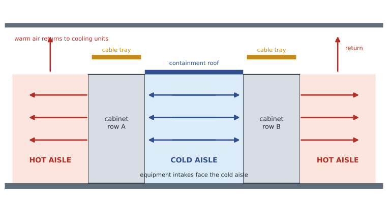
The aisle widths are set by access and by airflow. A cold aisle must be wide enough for people to install equipment from the front and, on raised floors, wide enough to hold perforated tiles; a common width is two floor tiles, about 1.2 m. A hot aisle must allow technicians to work at the rear of cabinets; about 0.9 to 1.2 m is common. Building codes and accessibility rules also set minimum clearances in front of electrical equipment, which may be wider.
Containment
Hot and cold aisles help, but air still mixes over the tops of the rows and around the ends. Containment closes the gap. In cold aisle containment, the cold aisle is capped with a roof and doors at each end, so cool air can only leave through the equipment. In hot aisle containment, the hot aisle is enclosed and its air ducted back to the cooling units, so the rest of the room stays at the cool supply temperature. Either way, the cooling units can run warmer supply air and use less energy, because the equipment no longer breathes a mix of hot and cold air.
Containment affects cabling directly. Cable trays and ladder racks above the cabinets must fit under or through the containment roof, and penetrations must be sealed. Fire suppression and lighting must still reach the aisle. Hot aisle containment means technicians working at the rear of cabinets work in hot air, often above 35 degrees Celsius, so the rear of the cabinet must be easy to work in quickly. The ICT designer must coordinate tray heights, containment panels and sprinkler heads on one drawing.
Blocking the leaks
Inside a cabinet, any open space allows hot exhaust air to recirculate to the front. Blanking panels fill unused rack units, and brush or grommet panels seal openings where cables pass through. Cables themselves are a major cause of blocked airflow: a thick bundle of cords hanging across the rear of servers blocks exhaust, and a mass of cables under a raised floor blocks supply air to the tiles. Good cable management is therefore part of the cooling design.
Practical rules follow. Route cords to the sides of the cabinet, not across the exhaust. Use cords of the right length rather than coiling long ones. Bring cables into cabinets from the top in overhead designs and seal the entry. On raised floors, keep under-floor cable trays in the hot aisle or under the cabinets and leave the cold aisle clear for air. Remove abandoned cables, which also reduce the fire load and are required to be removed by the electrical code in many cases.
How much air?
Every watt of electrical power used by IT equipment becomes heat, and that heat has to be carried away by air or liquid. For air cooling, the amount of air needed depends on the heat load and on the temperature rise of the air as it passes through the equipment. The relationship comes from the heat capacity of air.
Here P is the heat load, which for IT equipment equals its electrical power, and ΔT is the temperature rise across the equipment. The factor 1.2 is the approximate density of air times its specific heat in kilojoules per cubic metre per kelvin. Multiply cubic metres per second by 3,600 to get cubic metres per hour, the unit many cooling data sheets use.
Worked problem
Airflow for a server cabinet
A Harbourview server cabinet will draw 6 kW. The servers raise the air temperature by about 11 K from intake to exhaust. How much air must flow through the cabinet?
Show solution
- Use the metric formula: 6 ÷ (1.2 × 11) = 6 ÷ 13.2 ≈ 0.45 cubic metres per second.
- In cubic metres per hour: 0.45 × 3,600 ≈ 1,640.
- If cables block a third of the rear door, the servers must push the same air through a smaller opening, raising their fan power and temperature.
Answer: About 0.45 cubic metres per second, or roughly 1,640 cubic metres per hour, for one cabinet.
Heat loads are also given in other units. Mechanical engineers in North America often size cooling in tons of refrigeration, where one ton removes 12,000 BTU per hour, which is about 3.52 kW. One watt equals about 3.41 BTU per hour. An RCDD does not need to design the cooling, but should be able to convert a cabinet's power into these units so that the conversation with the mechanical engineer starts from shared numbers.
Worked problem
Converting the room load
The Harbourview data room will have 10 equipment cabinets averaging 5 kW each and two network cabinets at 2 kW each. What is the total load in kW, in BTU per hour and in tons?
Show solution
- IT load: 10 × 5 + 2 × 2 = 54 kW.
- In BTU per hour: 54 × 3,412 ≈ 184,000 BTU/h.
- In tons: 184,000 ÷ 12,000 ≈ 15.4 tons.
Answer: About 54 kW, 184,000 BTU per hour or roughly 15 tons, before adding lighting, people and losses in UPS and power distribution.
Temperature and humidity targets
Equipment manufacturers and the engineering society ASHRAE publish recommended and allowable ranges for the air entering IT equipment. The recommended inlet range commonly used for general equipment is roughly 18 to 27 degrees Celsius, with wider allowable ranges for short periods or for equipment rated for them. What matters is the temperature at the equipment intake, not the temperature of the room as a whole. Monitoring sensors should be placed at the front of cabinets at several heights, and the cabling designer should provide pathways and connections for them.
Rising power densities are changing the picture. Racks for high-performance computing and artificial intelligence workloads can draw tens of kilowatts each, beyond what air alone can remove economically. These use rear-door heat exchangers, in-row coolers close to the load or direct liquid cooling, in which coolant flows to cold plates on the processors. Liquid cooling brings water or coolant pipes into the cabinet area, which the cabling designer must keep separate from cable pathways, usually by running cables overhead and liquid under the floor or in separate overhead routes with drip protection.
The Harbourview layout
Daniel's layout puts the ten equipment cabinets in two rows of five, facing each other across a contained cold aisle, with the two network cabinets at the end of one row. In-row cooling units sit between cabinets, drawing warm air from the hot aisles and supplying cool air into the contained cold aisle. Ladder rack runs above each row, and a separate tray carries fibre trunks from each cabinet to the network row. The mechanical engineer sizes the cooling from Daniel's cabinet loads, and Priya sizes the power. The cabling drawings show every tray height and every containment penetration, so that the three trades can check for clashes before the contractor starts.
Cable entry is the other link between cabling and airflow. Overhead cables should enter cabinets through brush-sealed openings in the roof, sized for the cables expected in the cabinet's life. Under-floor cables should enter through brush grommets in the floor tile under the cabinet, never through open cut-outs that leak cold air into the hot aisle or the back of the cabinet.
Common mistakes
MistakeFacing all rows the same direction.
InsteadArrange rows front to front and back to back so that exhaust from one row does not feed the next.
MistakeLeaving empty rack units open.
InsteadInstall blanking panels so that hot exhaust cannot recirculate to the front.
MistakeRunning thick cable bundles across server exhausts.
InsteadRoute cords to the side managers and use correct lengths.
MistakeSupporting overhead trays on cabinets without a rating.
InsteadSupport trays from the structure unless the cabinet maker rates the cabinet to carry them.
Summary and key terms
- Equipment mounts on 19-inch rails measured in rack units of 44.45 mm; frames are open racks or enclosed cabinets.
- Cabinet width, depth and weight affect cable management, airflow and structure.
- Hot aisle and cold aisle layouts face rows front to front and back to back; containment stops hot and cold air from mixing.
- Cables and gaps can block airflow; blanking panels, sealed entries and good cord management are part of the cooling design.
- Air needed rises with heat load and falls with allowed temperature rise; heat loads convert between kW, BTU per hour and tons.
- Rack unit
- The standard unit of mounting height, 44.45 mm.
- Cabinet
- An enclosed equipment frame with sides and doors.
- Cold aisle
- The aisle where cool supply air reaches the fronts of equipment.
- Hot aisle
- The aisle where warm exhaust leaves the rear of equipment.
- Containment
- Physical barriers that separate hot and cold aisles to prevent mixing.
- Blanking panel
- A panel that fills unused rack units to stop air from recirculating.
Practice problems
Work each problem on paper first, then reveal the answer to check.
How tall is the mounting space in a 42U cabinet?
Show answer
42 × 44.45 mm ≈ 1,867 mm.
A cabinet draws 4 kW. Roughly how many tons of cooling is that?
Show answer
4 × 3,412 ≈ 13,650 BTU/h, or about 1.1 tons.
Why should under-floor cables stay out of the cold aisle?
Show answer
They block the supply air reaching the perforated tiles in front of the equipment.
Lesson quiz · 5 questions
Score 60% or more to complete this lesson.
Create a free account to save your progress, take quizzes and earn a certificate.