
RCDD-110 · Lesson 9 of 12 · 20 min
Electromagnetic interference and compatibility
▶ Video coming soon A video version of this lesson is on the way.
Priya Raman sends the latest electrical drawings for Harbourview. The mechanical penthouse has six variable-frequency drives for the air handlers. Each elevator machine room has a drive and a large motor. The clinic will install an imaging suite whose equipment comes with its own electromagnetic requirements, and the building's lighting uses LED fixtures with electronic drivers on every ceiling. Daniel lists every source and asks Roz which ones he should worry about. 'All of them, a little,' she says, 'and a few of them a lot. Electromagnetic compatibility is not about eliminating interference. It is about making sure every system in the building can live with every other one.'
Electromagnetic compatibility (EMC) is the ability of equipment and systems to work as intended in their electromagnetic environment without causing unacceptable interference to anything else. It has two sides: emissions, the interference a system produces, and immunity, its ability to tolerate interference from others. ICT cabling is involved in both. Poorly installed cabling can carry interference into network equipment, and cabling connected to equipment can act as an antenna that radiates the equipment's emissions. This lesson explains how interference couples, how the environment is classified, and how standards and regulations approach EMC.
Source, path and receiver
Every interference problem has three parts: a source that generates electromagnetic energy, a coupling path that carries it, and a receiver that is disturbed by it. Removing or weakening any one of the three solves the problem. Designers usually have the most control over the path, which is why separation, pathway choices, bonding and screening appear throughout the RCDD body of knowledge. Sometimes the most effective fix is at the source, such as filters on a variable-frequency drive specified by the electrical engineer, or at the receiver, such as equipment with higher immunity.
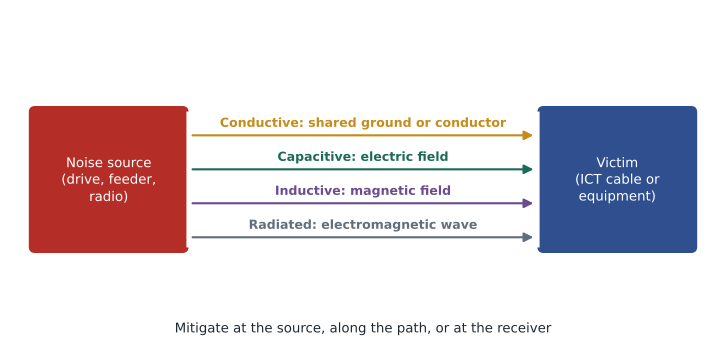
Four coupling mechanisms
Conductive coupling happens when the source and the victim share a conductor. Current from the source flowing through the shared conductor creates a voltage that appears in the victim's circuit. In ICT systems this is often a ground path: a bonding conductor or screen carrying current between two points at different potentials. This is the mechanism behind ground loops, and RCDD-113 covers it in detail.
Capacitive coupling, or electric field coupling, happens when a changing voltage on one conductor induces a current in a nearby conductor through the small capacitance between them. It rises with the rate of change of voltage, so sources with fast voltage edges, such as switching power supplies and the output of variable-frequency drives, are strong capacitive sources. It falls with distance and is blocked effectively by a grounded conductive screen between source and victim.
Inductive coupling, or magnetic field coupling, happens when a changing current in one conductor produces a magnetic field that induces a voltage in a loop formed by another circuit. It rises with the rate of change of current and the area of the victim loop. Large feeders, motor cables and transformers are strong magnetic sources at power frequencies and their harmonics. Twisted pairs resist inductive coupling because their small, alternating loops cancel the induced voltages, as Lesson 3 explained. Thin foil screens do little against low-frequency magnetic fields; distance and steel conduit or enclosures help more.
Radiated coupling happens when energy travels as an electromagnetic wave, which matters when the distance is large compared with the wavelength or the frequency is high. Radio transmitters, such as two-way radios, cellular devices and broadcast stations, are radiated sources. Cables can also act as antennas, picking up radiated fields or radiating the signals they carry. Good balance in a twisted pair, and properly bonded screens, reduce both.
| Mechanism | Typical sources | Most effective mitigation |
|---|---|---|
| Conductive | Shared ground or neutral paths, ground potential differences | Proper bonding design, avoiding shared paths |
| Capacitive (electric field) | Fast-switching voltages, drive outputs | Distance, grounded screens or metal barriers |
| Inductive (magnetic field) | High-current feeders, motors, transformers | Distance, small loops (twisting), steel enclosures |
| Radiated | Radio transmitters, high-frequency equipment | Balance, bonded screens, distance, filtering |
Common-mode and differential-mode interference
Interference can arrive on a cable in two ways, using the terms from Lesson 3. Common-mode interference appears equally on both conductors of a pair, or on all conductors of a cable, relative to ground. Differential-mode interference appears between the two conductors of a pair, exactly like a signal. Most external interference first appears as common mode. A well-balanced cabling system keeps it as common mode, where the receiver rejects it. Poor balance converts some of it to differential mode, where it corrupts the signal. That is why balance parameters such as TCL and ELTCTL are used to grade cabling for noisy environments.
Classifying the environment: MICE
Cabling standards describe the environment where cabling is installed with the MICE classification. MICE stands for Mechanical (shock, vibration, crushing), Ingress (dust and liquids), Climatic and chemical (temperature, humidity, corrosive substances, solar radiation), and Electromagnetic (electrostatic discharge, radiated and conducted interference). Each dimension is graded from 1 to 3. Level 1 describes a typical commercial office, level 2 a light industrial area and level 3 a harsh industrial environment. A space is described by its level in each dimension, such as M1I1C2E2.
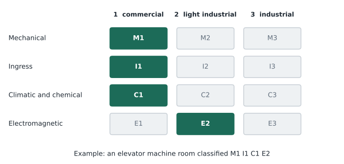
The electromagnetic levels set expected values for electrostatic discharge, radiated radio-frequency field strength, conducted interference on cables and fast transients. A designer uses the classification to choose components and installation methods. For an E2 or E3 environment, such as a mechanical room with drives or a factory floor, the designer might specify cabling with better balance, screened cabling with a proper bonding design, fibre instead of copper, or industrial-rated connectors and enclosures. Most of Harbourview is E1, but the mechanical penthouse, elevator machine rooms and parts of the imaging suite are closer to E2.
Emissions and immunity regulations
Equipment connected to ICT cabling must meet national EMC regulations. In Canada, ISED's Interference-Causing Equipment Standard ICES-003 sets emission limits for information technology equipment, aligned with the international CISPR 32 standard. Immunity requirements are set in international standards such as CISPR 35 for multimedia equipment and the IEC 61000-4 series of test methods. Medical electrical equipment has its own EMC standard within the IEC 60601 family, which matters for clinic floors.
Cabling itself is passive, so it is not usually certified for EMC on its own. But the way it is installed affects whether connected equipment meets its EMC performance in place. A balanced cabling system with good TCL, or a screened system with a correct bonding design, helps equipment stay within its emission limits and helps it tolerate the interference levels the MICE classification predicts.
Common sources in buildings
Variable-frequency drives are among the most troublesome sources in modern buildings. They switch large currents very quickly to control motor speed, producing high-frequency voltage and current components on the motor cables. The motor cable radiates, and the drive can inject noise into the building's ground system. The electrical engineer can reduce this at the source with filters, shielded motor cable, short cable runs and proper bonding. The ICT designer reduces it on the path by keeping cabling well away from drive output cables and their enclosures.
Other sources include elevators and large motors, which create strong magnetic fields when starting; transformers and switchgear; arc welding equipment; lighting drivers and dimmers; radio transmitters, including distributed antenna systems and two-way radio; and, in healthcare, imaging and diagnostic equipment with strong fields. Electrostatic discharge from people and equipment, and surges from lightning and power switching, are transient sources covered further in RCDD-113.
Worked problem
Estimating field strength from a radio
A two-way radio radiates an effective 5 W. A common far-field estimate of electric field strength is \(E \approx \sqrt{30 P}/d\) volts per metre, with \(P\) in watts and \(d\) in metres. What field does it produce 1 m from a telecommunications room rack?
Show solution
- \(E \approx \sqrt{30 \times 5}/1 = \sqrt{150} \approx 12.2\) V/m.
- At 3 m, \(E \approx 12.2/3 \approx 4.1\) V/m.
Answer: About 12 V/m at 1 m and 4 V/m at 3 m. A handheld radio used close to equipment can exceed the 3 V/m commonly expected in commercial environments, which is why some facilities restrict radio use near sensitive equipment.
Design approach
A practical EMC approach for ICT infrastructure has four steps. First, identify the sources and classify each space with MICE. Second, keep the coupling paths long: route ICT pathways away from major sources and maintain separation from power, as Lesson 10 describes. Third, choose media and components that suit each space: balanced cabling with good TCL for E1, screened cabling with proper bonding or fibre where E2 or E3 applies. Fourth, design the bonding and grounding system so that it does not create conductive coupling paths, as RCDD-113 explains.
Daniel annotates the floor plans with MICE levels. Most spaces are M1I1C1E1. The penthouse and elevator machine rooms are marked E2, and no horizontal cabling will pass through them; the few devices inside will be served by cables routed in steel conduit or by fibre to an industrial switch. The imaging suite gets a note to coordinate with the equipment vendor's site requirements, which often specify distances between cabling, power and the equipment, and which may call for fibre or screened cabling. Roz approves the annotations and adds them to the design basis as a separate EMC section.
Grounding, transients and immunity
Two kinds of interference are not continuous. Electrostatic discharge happens when a charged person or object touches equipment, producing a very fast pulse of current. Surges happen when lightning strikes nearby or when large loads switch, producing a high-energy pulse on power and communications conductors. Both can damage equipment as well as corrupt data. The MICE electromagnetic levels include expected values for both, and equipment immunity standards test against them.
The ICT designer's main defences against transients are proper bonding, which keeps all metalwork in a space at nearly the same potential so that a surge does not drive large currents through equipment; primary protectors where communications conductors enter a building, required by the electrical code for outside plant copper; and surge protective devices on power circuits. RCDD-113 covers these in detail. For this course, the key point is that EMC design and bonding design are linked: a poor bonding system can create both conductive coupling paths for continuous noise and dangerous paths for transient currents.
Exam focus: identifying the mechanism
Exam questions often describe a situation and ask which coupling mechanism is involved or which fix works best. Look for clues. A problem that appears only when a large motor starts suggests magnetic coupling from high current. Noise on a screened cable that is bonded at both ends to different ground systems suggests conductive coupling through a ground loop. Interference that appears when someone keys a radio nearby is radiated. Noise from a cable run alongside a drive's output cable, especially at high frequencies, is often capacitive. Matching the mechanism to the mitigation is the skill being tested.
Worked problem
Matching mechanism and fix
Network errors on a camera link occur whenever an elevator starts. The camera cable runs for 25 m alongside the elevator's motor feeder in an open tray. Which mechanism is likely, and which fix is most effective?
Show solution
- The problem correlates with high current when the motor starts, which points to magnetic coupling.
- Foil screening would help little at low frequencies.
- Rerouting the cable away from the feeder, or enclosing the feeder or cable in steel conduit, reduces magnetic coupling.
Answer: Inductive (magnetic) coupling; increase separation or use steel enclosure. Fibre to the camera would also solve it.
Common mistakes
MistakeAssuming foil screens stop all interference.
InsteadThin foil screens are effective against electric fields and high-frequency fields, but do little against low-frequency magnetic fields. Distance and steel help more there.
MistakeTreating EMC as only an emissions problem.
InsteadEMC includes immunity. Cabling and equipment must tolerate the environment as well as limit their own emissions.
MistakeClassifying a whole building as one environment.
InsteadMICE levels vary by space. Mechanical rooms and industrial areas need different treatment from offices.
MistakeIgnoring the source.
InsteadFilters and proper installation of drives and other sources, specified by the electrical engineer, often solve problems more cheaply than changing the cabling.
Summary and key terms
- EMC means systems can work in their electromagnetic environment without causing unacceptable interference; it covers emissions and immunity.
- Every interference problem has a source, a coupling path and a receiver; weakening any one solves it.
- Interference couples conductively, capacitively, inductively or by radiation, and each path has its own best mitigation.
- The MICE classification grades mechanical, ingress, climatic and electromagnetic conditions from 1 to 3 for each space.
- Equipment must meet national EMC rules, and cabling design and installation help equipment perform as intended in place.
- Electromagnetic compatibility (EMC)
- The ability of equipment to work in its electromagnetic environment without causing unacceptable interference.
- Emission
- Electromagnetic energy produced by a device or system that may interfere with others.
- Immunity
- The ability of a device or system to work correctly in the presence of electromagnetic interference.
- Inductive coupling
- Interference coupled through a changing magnetic field into a loop formed by the victim circuit.
- Capacitive coupling
- Interference coupled through the electric field between conductors at changing voltages.
- MICE
- A classification of installation environments by Mechanical, Ingress, Climatic and chemical, and Electromagnetic conditions.
Practice problems
Work each problem on paper first, then reveal the answer to check.
Which coupling mechanism do twisted pairs resist through their alternating loops?
Show answer
Inductive (magnetic field) coupling.
What does the E in a MICE classification describe?
Show answer
The electromagnetic environment: electrostatic discharge, radiated and conducted interference, and transients.
Name two ways to reduce interference from a variable-frequency drive.
Show answer
At the source with filters, shielded motor cable and proper bonding; on the path by keeping ICT cabling well away from the drive and its motor cables.
Lesson quiz · 5 questions
Score 60% or more to complete this lesson.
Create a free account to save your progress, take quizzes and earn a certificate.