
RCDD-110 · Lesson 8 of 12 · 21 min
Radio propagation basics for designers
▶ Video coming soon A video version of this lesson is on the way.
The college classrooms at Harbourview will have up to sixty students each, most of them with two or three wireless devices. The clinic floors need dependable coverage for wireless medical carts and staff phones, and the building's concrete core and lead-lined imaging rooms will block radio signals in ways the floor plans do not show. The wireless designer from the owner's network team will do the detailed predictive survey, but the cabling designer has to put an outlet, a pathway and enough power where every access point will go. Roz tells Daniel that he does not need to become a wireless engineer. 'But you need enough radio physics,' she says, 'to know when an access point location on a drawing makes no sense.'
Wireless systems are part of the ICT infrastructure an RCDD designs for. Access points need cabling, power and mounting; distributed antenna systems need fibre, coaxial cable and equipment space; and emergency responder radio systems may be required by code. This lesson covers the basics of radio propagation that a designer needs to plan those systems and to talk sensibly with wireless specialists. RCDD-114 applies them to wireless LAN, cellular and public safety designs.
Radio waves and wavelength
A radio signal is an electromagnetic wave: oscillating electric and magnetic fields travelling together at the speed of light. The same relationship from Lesson 1 links frequency and wavelength: \(\lambda = c/f\). A 2.4 GHz wireless LAN signal has a wavelength of about 12.5 cm; a 5.5 GHz signal about 5.5 cm; a 700 MHz public safety or cellular signal about 43 cm. Wavelength matters because it determines how a wave interacts with objects. Waves pass around objects much smaller than a wavelength, reflect from large flat surfaces, and are partly absorbed or blocked by materials depending on frequency.
| Use | Typical frequencies | Approximate wavelength |
|---|---|---|
| Public safety and some cellular | 700 to 900 MHz | 33 to 43 cm |
| Cellular mid-band | 1.7 to 3.8 GHz | 8 to 18 cm |
| Wireless LAN | 2.4 GHz | about 12.5 cm |
| Wireless LAN | 5 GHz band | about 5 to 6 cm |
| Wireless LAN | 6 GHz band | about 4.5 to 5 cm |
Use of the radio spectrum is regulated by national authorities. In Canada, Innovation, Science and Economic Development Canada (ISED) sets the rules for licence-exempt devices such as wireless LAN equipment and for licensed services. Rules limit transmit power, antenna gain and the bands each device may use. Designers rarely deal with these rules directly, but they explain why access points cannot simply be turned up to cover a larger area.
Free-space path loss
As a radio wave spreads out from an antenna, its power is spread over a larger and larger area. In free space, with nothing in the way, the power density falls with the square of the distance. Doubling the distance quarters the power density, a loss of about 6 dB. This is the inverse-square law, and it applies to all radiating waves.
The free-space path loss (FSPL) between two isotropic antennas combines this spreading with the size of the receiving antenna's effective capture area, which shrinks as frequency rises. With distance \(d\) in metres and frequency \(f\) in megahertz, it can be written as follows.
Worked problem
Path loss at two frequencies
What is the free-space path loss over 15 m at 2,437 MHz and at 5,500 MHz?
Show solution
- At 2,437 MHz: \(20 \log_{10} 15 = 23.5\); \(20 \log_{10} 2437 = 67.7\); total \(23.5 + 67.7 - 27.55 \approx 63.7\) dB.
- At 5,500 MHz: \(20 \log_{10} 5500 = 74.8\); total \(23.5 + 74.8 - 27.55 \approx 70.8\) dB.
Answer: About 63.7 dB and 70.8 dB. Over the same distance, the 5 GHz signal arrives about 7 dB weaker before any walls are counted.
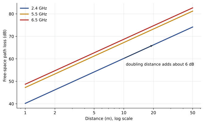
The fact that higher frequencies lose more is not because the waves are 'weaker'. It reflects the smaller capture area of a receiving antenna at shorter wavelengths. In practice, higher bands also suffer more from walls and bodies, which is why 5 GHz and 6 GHz cells are smaller than 2.4 GHz cells. For dense classrooms, small cells are an advantage: more access points can reuse the same channels without interfering, giving more total capacity.
Inside buildings: walls, bodies and multipath
Buildings are not free space. Every wall, floor, window, piece of furniture and person absorbs or reflects some of the signal. The loss through a material depends on its composition, thickness and the frequency. Typical rough values are a few decibels through a drywall partition, more through brick or block, and ten to fifteen decibels or much more through reinforced concrete, metal-coated glass and elevator shafts. Lead shielding in imaging rooms and metal-backed partitions can block signals almost entirely. Wireless designers use measured or published attenuation values for each material in predictive design software.
Indoor propagation is often described with a path loss exponent. In free space, loss rises with the square of distance, an exponent of 2. In a cluttered office, the effective exponent may be 3 or more, meaning loss rises much faster with distance than free-space calculations suggest. This is why rules of thumb about access point range from manufacturers' brochures rarely match real buildings.
Radio waves also reflect from walls, floors and metal objects, so a receiver hears the same signal arriving by several paths with different delays. This is multipath. In older radio systems it caused fading, where reflected waves cancelled the direct wave at some locations. Modern wireless LAN and cellular systems use multiple antennas and signal processing (MIMO) to turn multipath into an advantage, sending several data streams at once over different paths. They still need enough signal strength and signal-to-noise ratio at the receiver.
Antennas and EIRP
An antenna does not create power. It concentrates the power it receives from the transmitter in some directions at the expense of others. Antenna gain, expressed in dBi, compares the strength in the antenna's strongest direction with that of an ideal isotropic antenna radiating equally in all directions. An omnidirectional ceiling antenna might have a gain of 3 to 5 dBi; a directional patch antenna for a long corridor might have 8 to 12 dBi.
The effective isotropic radiated power (EIRP) is the transmitter output plus antenna gain, minus any cable and connector losses between them. Regulators limit EIRP, not just transmitter power, so a higher-gain antenna may require a lower transmitter setting. EIRP is the starting point of a radio link budget, exactly as launch power is for a fibre link.
Worked problem
A radio link budget
An access point transmits 17 dBm into an internal 4 dBi antenna with no cable loss. A client 15 m away at 5,500 MHz is behind one drywall partition (4 dB) and has a 0 dBi antenna. The client needs at least −67 dBm for the data rates the design targets. Is the signal adequate?
Show solution
- EIRP = 17 + 4 = 21 dBm.
- Free-space path loss = 70.8 dB (from the earlier example).
- Received power = 21 − 70.8 − 4 + 0 = −53.8 dBm.
- Margin = −53.8 − (−67) = 13.2 dB.
Answer: About −54 dBm with 13 dB of margin, so the signal is strong enough on paper. Real designs confirm this with a predictive model and a site survey.
Note that the design target is not 'a signal'. It is a minimum received signal strength, often combined with a minimum signal-to-noise ratio, chosen to support particular data rates and applications such as voice. Wireless designers set those targets, and the cabling designer must put access points where those targets can be met, which usually means more access points, closer together, than people expect.
Fresnel zones and line of sight
For radio links between buildings, or long corridors with directional antennas, a clear straight line between the antennas is not enough. A radio wave occupies an ellipsoid-shaped region around the direct path called the first Fresnel zone. If obstacles intrude into much of this zone, the signal is weakened even when the antennas can see each other. At the midpoint of a path of length \(D\) in kilometres at frequency \(f\) in gigahertz, the radius of the first Fresnel zone in metres is about \(r = 8.66\sqrt{D/f}\). Designers aim to keep most of that zone clear, often at least six tenths of the radius.
Worked problem
Clearance for a building-to-building link
A 5.8 GHz point-to-point link is planned over the 400 m between Harbourview and the college building. What is the first Fresnel zone radius at the midpoint?
Show solution
- \(r = 8.66 \sqrt{0.4/5.8} = 8.66 \times 0.263 \approx 2.27\) m.
Answer: About 2.3 m. Trees or a roof edge within a metre or two of the direct line could weaken the link. At Harbourview the campus link is fibre, and a radio link could serve as a backup path.
Interference and noise
Every radio receiver hears noise: thermal noise from its own electronics and the environment, and interference from other transmitters. In licence-exempt bands such as wireless LAN, neighbouring networks, other access points on the same channel, Bluetooth devices, microwave ovens in the 2.4 GHz band and many other devices share the spectrum. As in cabling, capacity depends on signal-to-noise ratio, not just signal strength. A strong signal in a noisy environment can perform worse than a moderate signal in a quiet one.
This is why wireless designs control co-channel interference by choosing channels, adjusting transmit power and placing access points so that cells overlap enough for roaming but not so much that they interfere. It is also why turning up the power on every access point to 'improve coverage' often makes performance worse.
What the cabling designer contributes
Back at the drawings, Daniel checks the access point locations the wireless designer has marked on the clinic floors. Two are inside a corridor lined with lead-shielded imaging rooms, which makes sense, because the shielding will stop them covering the rooms anyway. One is mounted above a metal ceiling grid in the plenum, which would block much of its signal, so Daniel flags it. Each access point gets two Category 6A outlets, so that a future access point with two uplinks or a second radio can be added without new cabling, and the telecommunications room serving each floor gets enough PoE capacity and cooling. Roz adds one more requirement: a cabling grid of spare outlets in the classroom ceilings so the access point layout can change after the first site survey without new horizontal runs.
Exam focus: radio arithmetic
Radio questions on the exam usually need only three tools: the wavelength formula, the free-space path loss formula and the link budget. Remember that path loss grows by 6 dB for each doubling of distance and by 20 dB for each tenfold increase in distance or frequency. Remember that EIRP is the power that matters for regulations and for the start of the budget. And remember that the received signal must be compared with a target that includes enough margin for walls, people and fading that a free-space calculation ignores.
Common mistakes
MistakeAssuming access point range is fixed by the product.
InsteadRange depends on frequency, walls, antenna gain, client devices and the target signal level. Building materials change it greatly.
MistakeThinking higher transmit power always improves coverage.
InsteadMore power raises interference with neighbouring cells. Capacity depends on signal-to-noise ratio, not only signal strength.
MistakeTreating antenna gain as extra power.
InsteadGain concentrates power in some directions. EIRP limits mean a higher-gain antenna may need a lower transmitter setting.
MistakeIgnoring the Fresnel zone on outdoor links.
InsteadClear line of sight is not enough; most of the first Fresnel zone should be clear of obstacles.
Summary and key terms
- Radio waves follow the same frequency and wavelength relationship as other signals; wavelength affects how they interact with objects.
- Free-space path loss rises by about 6 dB for each doubling of distance and is higher at higher frequencies.
- Inside buildings, walls, bodies and metal add loss, and multipath creates both problems and opportunities for MIMO systems.
- EIRP is transmitter power plus antenna gain minus cable loss, and is the starting point of a radio link budget.
- Outdoor links need a clear first Fresnel zone, and all radio designs depend on signal-to-noise ratio as well as signal strength.
- Free-space path loss
- The loss between two isotropic antennas in free space, increasing with distance and frequency.
- EIRP
- Effective isotropic radiated power: transmitter power plus antenna gain minus feed losses.
- Multipath
- Reception of a signal by several paths of different lengths, caused by reflections.
- MIMO
- Multiple input, multiple output: radio systems that use several antennas to send several streams or improve reliability.
- Fresnel zone
- An ellipsoid-shaped region around the direct path between antennas that should be kept largely clear.
- Path loss exponent
- A number describing how quickly loss rises with distance; 2 in free space, often 3 or more indoors.
Practice problems
Work each problem on paper first, then reveal the answer to check.
By how much does free-space path loss rise when the distance doubles?
Show answer
About 6 dB.
What is the wavelength of a 900 MHz signal in air?
Show answer
\(\lambda = 3 \times 10^{8} / 9 \times 10^{8} \approx 0.33\) m.
A transmitter produces 20 dBm, the antenna has 6 dBi of gain and the cable loses 2 dB. What is the EIRP?
Show answer
20 + 6 − 2 = 24 dBm.
Lesson quiz · 5 questions
Score 60% or more to complete this lesson.
Create a free account to save your progress, take quizzes and earn a certificate.