
RCDD-110 · Lesson 6 of 12 · 20 min
Optical fibre fundamentals: modes, wavelengths and loss
▶ Video coming soon A video version of this lesson is on the way.
Harbourview needs fibre in three places: a backbone from the main equipment room on the ground floor to the telecommunications room on each upper floor, a campus link to the existing college building 400 m away, and short connections inside the data room. The owner's network team has asked for 'whatever fibre we will not regret in fifteen years'. Daniel has terminated plenty of fibre, but he has always been told which type to use. Now he has to choose, and to justify the choice. Roz starts with a question: 'Why can light go round a corner inside a strand of glass at all?'
Optical fibre carries information as pulses of light through a strand of extremely pure glass. It offers far more bandwidth than copper over far longer distances, is immune to electromagnetic interference, carries no electrical current between buildings and is lighter and thinner for the capacity it provides. Its weaknesses are mechanical and practical: it can be damaged by tight bends and crushing, its connectors must be kept clean, and the electronics that drive it cost more than copper transceivers at short distances. This lesson explains how fibre guides light, the types designers choose between, and where its loss comes from.
How fibre guides light
A fibre has two layers of glass. The core, at the centre, carries the light. The cladding around it has a slightly lower refractive index, which is a measure of how much the glass slows light down compared with a vacuum. A protective coating, usually acrylate, is applied over the cladding to 250 micrometres or 200 micrometres in diameter, and cables add buffers, strength members and jackets on top of that.
When light inside the core hits the boundary with the cladding at a shallow enough angle, it is reflected back into the core completely. This is total internal reflection. It only happens if the angle of incidence, measured from a line perpendicular to the boundary, is greater than the critical angle, which depends on the two refractive indices: \(\sin\theta_c = n_2/n_1\). Light entering the fibre within a cone of acceptance is guided; light entering at a steeper angle escapes into the cladding and is lost. The size of the acceptance cone is described by the numerical aperture.
Worked problem
Critical angle
A fibre has a core index of 1.475 and a cladding index of 1.460. What are the critical angle and the numerical aperture?
Show solution
- \(\sin\theta_c = 1.460/1.475 = 0.9898\), so \(\theta_c \approx 81.8\) degrees.
- \(\text{NA} = \sqrt{1.475^{2} - 1.460^{2}} = \sqrt{2.1756 - 2.1316} = \sqrt{0.0440} \approx 0.21\).
Answer: The critical angle is about 82 degrees and the NA about 0.21, typical of 50 micrometre multimode fibre. Only light travelling nearly parallel to the axis is guided.
Because the guiding depends on angles, bending the fibre too tightly changes the angle at which light meets the boundary. Some light then falls below the critical angle and escapes. This is bend loss, and it explains why fibre cables have minimum bend radius limits and why bend-insensitive fibres, which use a modified index profile to hold the light in more tightly, are popular in dense installations.
Modes: multimode and singlemode
Light in a fibre travels in a limited number of distinct paths called modes. The number of modes depends on the core diameter, the numerical aperture and the wavelength. A large core supports many modes, so it is called multimode fibre. A very small core, around 8 to 9 micrometres, supports only one mode at the wavelengths used, so it is called singlemode fibre. Both types have the same 125 micrometre cladding diameter, so they look alike to the naked eye and use similar connector ferrules.
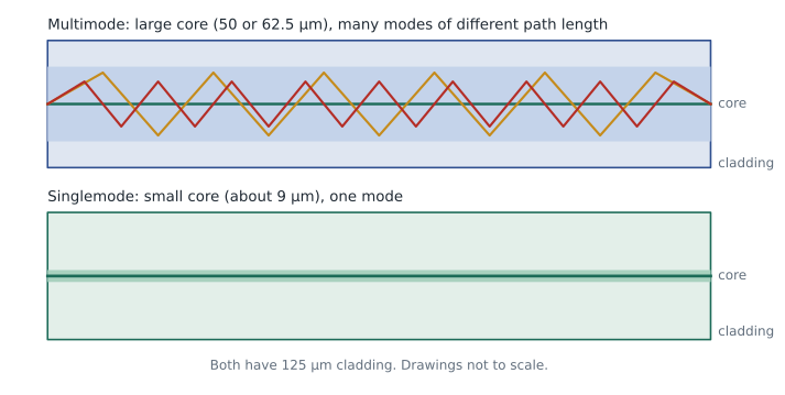
Different modes travel different distances. In a step-index multimode fibre, where the core has a uniform refractive index, a mode that zigzags steeply takes much longer to reach the far end than one travelling straight down the axis. A short pulse at the input therefore spreads out in time as it travels. This is modal dispersion. If pulses spread too far, they overlap and the receiver cannot tell them apart, which limits data rate and distance.
Modern multimode fibre reduces modal dispersion by using a graded-index core. The refractive index is highest at the centre and falls gradually toward the cladding. Light travelling the longer, outer paths moves through lower-index glass, where it travels faster, so it catches up with light on the shorter central path. Careful control of this profile is what distinguishes the higher grades of multimode fibre.
Singlemode fibre has no modal dispersion because it carries only one mode. Its bandwidth is limited instead by chromatic dispersion: different wavelengths in the light source travel at slightly different speeds. With narrow-linewidth lasers, singlemode fibre supports very high data rates over tens of kilometres, which is why it is the standard choice for campus, metropolitan and long-haul networks, and increasingly inside data centres.
Fibre types designers specify
Multimode fibres are graded by the OM classes in ISO/IEC 11801 and the matching TIA designations. They are rated by effective modal bandwidth (EMB), measured in megahertz-kilometres at a given wavelength: the product of the bandwidth and the length that a fibre can support.
| Type | Core | Main wavelengths | Notes |
|---|---|---|---|
| OM1 | 62.5 micrometres | 850 and 1300 nm | Legacy; not recommended for new designs |
| OM2 | 50 micrometres | 850 and 1300 nm | Legacy |
| OM3 | 50 micrometres | 850 nm, laser-optimized | Effective modal bandwidth of 2,000 MHz·km at 850 nm |
| OM4 | 50 micrometres | 850 nm, laser-optimized | Effective modal bandwidth of 4,700 MHz·km at 850 nm |
| OM5 | 50 micrometres | 850 to 953 nm (wideband) | Supports short-wavelength multiplexing |
| OS1a and OS2 | about 9 micrometres | 1310 and 1550 nm (and others) | Singlemode; OS2 used widely inside and outside buildings |
Laser-optimized multimode fibres, OM3 and newer, are designed for vertical-cavity surface-emitting lasers (VCSELs), the inexpensive light sources used by short-reach multimode transceivers at 850 nm. The higher the grade, the further a given application can reach. For example, a common 10 gigabit multimode application reaches about 300 m on OM3 and about 400 m on OM4. Higher-speed multimode applications have much shorter reaches, often 100 m or less, which is why many large data centres now use singlemode even for short links.
Fibre cable jackets are often colour-coded by type in premises cabling: aqua is common for OM3 and OM4, sometimes violet for OM4, lime green for OM5 and yellow for singlemode. Colour coding is a convention, not a guarantee. The printed legend on the jacket and the manufacturer's documentation identify the fibre.
Wavelengths and the attenuation curve
Glass absorbs and scatters light differently at different wavelengths. Premises networks use a few well-established operating windows where loss is low and practical light sources exist: 850 nm and 1300 nm for multimode, and 1310 nm and 1550 nm for singlemode, with other wavelengths used for multiplexing.
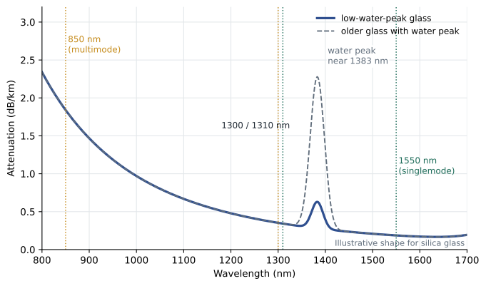
Two main mechanisms cause loss inside the glass. Rayleigh scattering comes from tiny variations in the glass structure that scatter light in all directions. It falls sharply with wavelength, roughly as \(1/\lambda^{4}\), which is why loss is much lower at 1550 nm than at 850 nm. Absorption comes from impurities and from the glass itself. Older fibres had a pronounced absorption peak near 1383 nm caused by water molecules trapped in the glass; low-water-peak fibres such as those meeting ITU-T G.652.D remove most of it.
The attenuation coefficient of a fibre is quoted in decibels per kilometre. Typical cabled values are a few dB per kilometre for multimode at 850 nm and well under 1 dB per kilometre for singlemode. Cabling standards set maximum values for design, which are higher than the typical values in data sheets. Lesson 7 uses those maximum values to build loss budgets.
Loss outside the glass
In premises networks, the fibre itself is rarely the largest source of loss. Most loss comes from connections, splices and installation damage. A mated connector pair loses light because the two cores are never perfectly aligned, the end faces are never perfectly clean or flat, and some light reflects at the gap. Splices, which join two fibres permanently, lose less: a good fusion splice typically loses well under a tenth of a decibel. Bends cause two kinds of loss. Macrobends are visible curves tighter than the minimum bend radius. Microbends are tiny distortions caused by pressure on the fibre, for example from over-tightened ties or a crushed cable, and they can cause significant loss even when the cable looks undamaged.
Contamination is the leading cause of fibre link failures. A speck of dust a few micrometres across can block a large part of a singlemode core. Inspection and cleaning before every mating, using a fibre inspection scope, is the single most effective practice for keeping fibre links healthy, and current standards and test procedures expect it.
Choosing fibre at Harbourview
Roz and Daniel work through the three uses. Inside the data room, links between switches and servers are short, but the network team expects to move to higher speeds that have shorter multimode reaches. Inside the building, the backbone runs are under 100 m. For the campus link of 400 m, multimode would limit future speeds. Roz's recommendation is a hybrid backbone with singlemode for the campus link and the riser backbone, plus OM4 multimode in the riser for any existing equipment that needs it, and singlemode-ready pathways in the data room. 'Singlemode glass is cheaper than multimode,' she points out. 'The optics cost more today, but the glass will outlive several generations of optics.' The decision will be confirmed with the network team, and the loss budgets in Lesson 7 will check that each link works.
Exam focus: choosing between fibre types
Questions about fibre types usually describe a distance, a speed and sometimes an expected upgrade, and ask which fibre to choose. Work through them in order. First, how far must the link reach? Beyond a few hundred metres, singlemode is almost always the answer. Second, how fast must it go, now and later? Higher-speed multimode applications have shorter reaches, so a link that works for 10 gigabits on OM3 may not work for 100 gigabits. Third, what equipment exists? Legacy equipment may need OM1 or OM2 compatible links, which is a reason to keep some multimode in a backbone. Fourth, what is the cost balance? Multimode transceivers have traditionally been cheaper at short distances, but that gap has narrowed.
Be careful with mixed-type questions. A 62.5 micrometre fibre should never be connected to a 50 micrometre fibre in a link, and multimode should never be connected to singlemode. The core mismatch causes large loss, especially from the larger core into the smaller one. Where both types are installed, colour coding, labelling and different connector or adapter styles help prevent mistakes.
Worked problem
Choosing for the riser
A riser backbone link is 85 m long. The owner's equipment uses 10 gigabit multimode optics today, and the network team expects 100 gigabit links within ten years. Which fibre types should the backbone include?
Show solution
- At 85 m, OM4 supports common 10 gigabit and some 100 gigabit multimode applications.
- Singlemode supports every expected speed at this length and beyond.
- Including both lets today's optics be reused and gives a clear upgrade path.
Answer: A hybrid cable with OM4 and OS2 strands is a sound choice, which is the decision made at Harbourview.
Common mistakes
MistakeThinking singlemode and multimode can be mixed in one link.
InsteadTheir core sizes differ greatly. Connecting multimode to singlemode causes very large loss in one direction and is not allowed in a link.
MistakeAssuming loss is mostly in the glass in building networks.
InsteadIn short premises links, connectors, splices, bends and contamination usually cause most of the loss.
MistakeTreating jacket colour as proof of fibre type.
InsteadColour is a convention. Check the printed legend and documentation.
MistakeIgnoring bend radius once a cable passes testing.
InsteadMicrobends and macrobends can develop later from cable management changes and cause intermittent loss.
Summary and key terms
- Fibre guides light by total internal reflection at the boundary between a higher-index core and a lower-index cladding.
- Multimode fibre has a 50 or 62.5 micrometre core and many modes; singlemode has a core of about 9 micrometres and one mode.
- Graded-index multimode reduces modal dispersion; OM3, OM4 and OM5 are laser-optimized grades rated by effective modal bandwidth.
- Attenuation falls with wavelength because Rayleigh scattering decreases; 850 and 1300 nm are used for multimode, 1310 and 1550 nm for singlemode.
- In premises networks most loss comes from connectors, splices, bends and contamination, so inspection and cleaning are essential.
- Total internal reflection
- Complete reflection of light at a boundary with a lower-index material when the angle exceeds the critical angle.
- Numerical aperture
- A measure of the range of angles over which a fibre accepts light.
- Mode
- A distinct path or field pattern in which light can travel through a fibre.
- Modal dispersion
- Spreading of a pulse because different modes take different times to travel the fibre.
- Effective modal bandwidth (EMB)
- The bandwidth-distance capability of a laser-optimized multimode fibre, in MHz·km.
- Microbend
- A small, local distortion of the fibre that causes loss, often from pressure on the cable.
Practice problems
Work each problem on paper first, then reveal the answer to check.
What is the cladding diameter of both common singlemode and multimode fibres?
Show answer
125 micrometres.
Why is attenuation lower at 1550 nm than at 1310 nm?
Show answer
Rayleigh scattering falls roughly as \(1/\lambda^{4}\), so longer wavelengths scatter less.
Why does a graded-index core reduce modal dispersion?
Show answer
Light on longer outer paths travels through lower-index glass where it moves faster, so it arrives at nearly the same time as light on the shorter central path.
Lesson quiz · 5 questions
Score 60% or more to complete this lesson.
Create a free account to save your progress, take quizzes and earn a certificate.