
RCDD-110 · Lesson 12 of 12 · 22 min
Applying transmission principles to design decisions
▶ Video coming soon A video version of this lesson is on the way.
Three months after Daniel's first morning on Harbourview, Roz asks him to write the transmission section of the project's design basis on his own and present it to the owner's network team, Priya and Marcus. 'You have the pieces,' she says. 'Now put them together the way a client needs to hear them: what we decided, why, and how we will know it worked.' This lesson follows Daniel through that document. It pulls together every topic in the course and shows how transmission principles turn into defensible design decisions, the kind the RCDD exam expects you to reason through.
A design basis is the record of the requirements, assumptions and decisions behind a design. It lets the owner, the other designers, the contractor and future maintainers understand why the infrastructure is the way it is. For transmission, it should connect each owner requirement to an application, each application to a cabling class and media type, each class to the installation conditions that protect it, and each of those to a verification method. That chain is the requirement chain Daniel wrote in his notebook in Lesson 1.
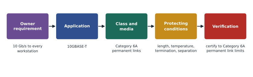
Step 1: Requirements and applications
Daniel begins with the owner's stated requirements and turns each into one or more named applications. Ten gigabits per second to every clinic workstation and classroom display becomes 10GBASE-T. Wireless coverage with high capacity in classrooms becomes multigigabit access point uplinks, 2.5GBASE-T and 5GBASE-T today with 10GBASE-T expected, and high-power PoE. Imaging equipment becomes the vendor's specified interfaces. The campus link becomes singlemode Ethernet at 10 and later 100 gigabits per second. The data room becomes short multimode and singlemode links for switches and servers, with the network team's expected upgrades.
He also records the design life, fifteen years, and the assumption that the electronics will be replaced at least three times in that period. That assumption drives several later decisions, because it means the cabling must support applications that are not yet installed.
Step 2: Cabling classes and media
For horizontal cabling, Daniel specifies Category 6A permanent links, from a single manufacturer's warranted system, because 10GBASE-T over 100 m needs a 500 MHz channel with controlled alien crosstalk (Lessons 1, 4 and 5). U/UTP is used on the general floors, which are classified E1, and F/UTP in the imaging equipment room, classified E2, with a full screened system and bonding (Lessons 9 and 11).
For backbone and campus fibre, he specifies singlemode OS2 for the riser and campus link, with OM4 multimode in the riser for legacy equipment (Lesson 6). For the data room, he specifies low-loss connectors so the most demanding multimode applications the network team expects fit their channel limits (Lesson 7). For the mechanical penthouse and elevator machine rooms, he specifies fibre to industrial switches (Lesson 9).
| Area | Environment | Media and grade | Key reason |
|---|---|---|---|
| Clinic and classroom floors | M1I1C1E1 | Category 6A U/UTP | 10GBASE-T at 100 m, multigigabit wireless, PoE |
| Imaging equipment room | M1I1C1E2 | Category 6A F/UTP, full screened system | Vendor requirement, E2 environment, low emissions |
| Riser backbone | Riser | OS2 singlemode plus OM4 | Long life, future speeds, legacy support |
| Campus link | Outside plant | OS2 singlemode | 400 m distance, separate ground systems |
| Data room | M1I1C1E1 | OM4 and OS2 with low-loss connectors; some Category 8 | Tight channel loss limits; 25G/40GBASE-T option |
| Penthouse and machine rooms | E2 | Fibre to industrial switches | Drives and motors, hostile to copper |
Step 3: Conditions that protect the channel
A cabling class guarantees performance only under the conditions the standard assumes: lengths within limits, temperature near 20 degrees Celsius or derated, correct termination, separation from interference sources and so on. Daniel's next section lists the conditions the design relies on and how each is achieved.
Length and temperature come first. The longest horizontal link on the plans is 84 m, within the 90 m permanent link limit. But several links run through a ceiling space above the kitchen of the clinic's staff area, where temperatures could reach 40 degrees Celsius in summer. Insertion loss rises with temperature (Lesson 4), so Daniel checks those links.
Worked problem
Temperature derating
A Category 6A U/UTP permanent link is 78 m long. The manufacturer gives an insertion loss derating factor of 0.004 per degree Celsius above 20 degrees for this cable, applied to the cable length. What is the equivalent length at 40 degrees, and is the link within the 90 m limit?
Show solution
- Temperature rise: \(40 - 20 = 20\) degrees.
- Increase in loss: \(20 \times 0.004 = 0.08\), so the cable behaves as if it were \(1.08\) times as long.
- Equivalent length: \(78 \times 1.08 = 84.2\) m.
Answer: About 84 m equivalent, still within the 90 m limit. An 86 m link in the same space would exceed it at 40 degrees and would need rerouting or a shorter path.
Power over Ethernet adds heat. Bundles of cables carrying high-power PoE warm up, and the innermost cables of a large bundle warm most. Daniel limits bundle sizes in the ceiling pathways near the classrooms, where many access points and displays draw power, and specifies larger-conductor Category 6A cable, which heats less. RCDD-112 develops the PoE bundle analysis further.
Termination quality protects NEXT and return loss (Lessons 3 and 4). The specification requires compliance with each connector manufacturer's untwist and bend radius limits, and detailed review of the first links terminated on each floor. Separation protects against interference (Lesson 10). The project separation standard from the third-floor coordination meeting becomes part of the specification, with drawings showing where pathways cross power at right angles and where metal barriers are used. MICE classifications are shown on the floor plans (Lesson 9).
Step 4: Budgets and margins
Daniel includes the fibre loss budgets from Lesson 7 in a table, one row per link group, with the wavelengths, the calculated budget, the test method and the required launch condition. For the campus link, the budget of 2.34 dB at 1310 nm leaves a large margin against singlemode applications, which typically allow several decibels more. For the data room multimode channels, the budget with low-loss connectors is checked against the tightest application limit the network team expects, with the result that no channel may have more than three mated pairs.
He also includes a short wireless section, prepared with the wireless designer, showing the design signal level and signal-to-noise targets, the access point density in classrooms and the two-outlet standard at each access point location (Lesson 8). Its purpose in a transmission design basis is to show that the cabling and power have been sized for the wireless design, not to repeat the wireless designer's work.
Worked problem
Is the classroom channel budget for PoE adequate?
A classroom ceiling pathway carries a bundle of 24 Category 6A cables. The manufacturer's guidance allows bundles of up to 48 cables carrying the highest PoE class in this pathway type and ambient temperature without further derating. Does the design need a change?
Show solution
- The bundle size, 24, is half the manufacturer's guidance limit of 48.
- The pathway and ambient match the conditions of the guidance.
Answer: No change is needed. The design records the guidance used, so that future additions to the bundle can be checked against it.
Step 5: Verification
The final part of the transmission section explains how the owner will know the design worked. Every copper permanent link is certified with a field tester against the Category 6A permanent link limits of the named standard, with all parameters reported, including margins (Lesson 4). A sample of links in the largest bundles is tested for alien crosstalk. Every fibre link is tested with an optical loss test set at both wavelengths, using the one-cord reference method and, for multimode, an encircled flux launch, and compared with its budget. Backbone and campus links are also tested with an OTDR, and the traces are kept as records (Lesson 7). In the screened area, screen continuity and bonding are verified (Lesson 11).
Daniel adds a requirement that the test reports be delivered in the tester's native format as well as as printed reports, so the owner's staff can review any link later, and that the reports show the tester's calibration date and the software version of the limit tables. Small details like these decide whether a test result can be trusted years later when someone asks why a link is misbehaving.
| What is tested | Method | Pass criterion |
|---|---|---|
| Copper permanent links | Field certification tester, permanent link adapter | All parameters within Category 6A permanent link limits |
| Sample of links in large bundles | Alien crosstalk test | Within PS ANEXT and PS AACR-F limits |
| Fibre links | Optical loss test set, one-cord reference, encircled flux launch for multimode | Measured loss at or below each link's budget |
| Backbone and campus fibre | OTDR at two wavelengths | Events within component allowances; trace recorded |
| Screened cabling area | Screen continuity and bonding checks | Continuous screen, bonding connections verified |
Presenting the decisions
In the meeting, the network team's lead asks why they should not simply install Category 8 everywhere 'to be safe'. Daniel uses the requirement chain to answer. Category 8 is a 30 m, two-connector data centre channel, so it would not support 100 m horizontal links at all; the applications the owner needs are fully supported by Category 6A; and the extra cost, size and stiffness would bring no benefit. Priya asks whether the separation standard will add cost. Daniel shows that most of it is met by routing choices already on the drawings, and that the remaining barriers are short. Marcus asks what the contractor needs to do differently from a typical job. Daniel points to three items: termination review on the first links, screened cords in the imaging room and the fibre test method.
After the meeting, Roz has one comment. 'You did not tell them anything about physics,' she says, 'and every decision you made was physics. That is the job.' Daniel's next course, RCDD-111, turns from what travels through the cabling to the spaces and pathways that hold it.
Exam focus: putting it together
Scenario questions on the exam often combine several topics from this course in one situation. A typical example describes a building, a set of applications and an environment, and asks which media, grade or installation measure is most appropriate. The way to answer is the requirement chain. Identify the application and its cabling class. Check the environment for interference and temperature. Check distances for copper limits and fibre budgets. Then choose the option that meets the requirement with the fewest assumptions. The wrong answers are usually either too little (a grade that will not support the application) or the wrong kind of too much (a grade or construction that does not fit the channel model or the environment).
Worked problem
A combined scenario
A new school wing needs 10GBASE-T to classroom displays 70 m from the telecommunications room, a camera on a mechanical room wall next to two large drives and a link to a gymnasium 180 m away. Which media fit each requirement?
Show solution
- Classroom displays at 70 m with 10GBASE-T: Category 6A permanent links.
- Camera beside large drives in an E2 space: fibre to an industrial switch, or screened Category 6A routed away from the drive cables with proper bonding.
- Gymnasium at 180 m: beyond the 100 m copper channel, so fibre, singlemode or OM4 depending on speed and future plans.
Answer: Category 6A to the classrooms, fibre or carefully bonded screened cabling at the mechanical room, and fibre to the gymnasium.
Common mistakes
MistakeChoosing media by habit or by the highest grade available.
InsteadWork from the applications and environment. The highest grade is not always suitable, as Category 8 shows.
MistakeTreating standard conditions as guaranteed.
InsteadTemperature, PoE heating, termination quality and interference all change real performance. Check each condition the class relies on.
MistakeLeaving verification to the contractor.
InsteadThe design must state test methods, limits and reporting requirements, or results cannot be compared with the design.
MistakeWriting decisions without reasons.
InsteadA design basis should explain why. Future owners and designers need the reasoning to make changes safely.
Summary and key terms
- A design basis traces owner requirements to applications, cabling classes and media, protecting conditions and verification.
- Media choices follow from applications, distance, environment and expected life, not from habit or the highest available grade.
- Temperature, PoE heating, termination quality and separation are conditions the cabling class depends on, and the design must address each.
- Loss budgets, wireless targets and PoE bundle checks show that margins are adequate.
- Verification states the test method, the limits, the sample and the reporting requirements so the owner can confirm the design worked.
- Design basis
- A document recording the requirements, assumptions and decisions behind a design.
- Requirement chain
- The trace from an owner requirement through application, cabling class and conditions to verification.
- Temperature derating
- Adjusting allowed length or expected loss to account for operating temperatures above the standard reference.
- Design life
- The period over which the infrastructure is expected to support the owner's applications.
- Verification plan
- The set of tests and acceptance criteria that confirm installed infrastructure meets the design.
Practice problems
Work each problem on paper first, then reveal the answer to check.
A 70 m link runs where temperatures reach 45 degrees. With a derating factor of 0.004 per degree above 20, what is its equivalent length?
Show answer
25 × 0.004 = 0.10, so 70 × 1.10 = 77 m.
Why does the design basis record the manufacturer's PoE bundle guidance?
Show answer
So that future additions to the bundle can be checked against the same guidance.
Give the requirement chain for 10 Gb/s to every workstation.
Show answer
Owner requirement: 10 Gb/s. Application: 10GBASE-T. Class: Category 6A permanent links. Conditions: lengths, temperature, termination, separation. Verification: certification to Category 6A permanent link limits.
Lesson quiz · 5 questions
Score 60% or more to complete this lesson.
Create a free account to save your progress, take quizzes and earn a certificate.