
RCDD-110 · Lesson 3 of 12 · 20 min
Balanced twisted-pair transmission
▶ Video coming soon A video version of this lesson is on the way.
On the second floor of Harbourview, the clinic will have imaging equipment, elevator machine rooms will sit at each end of the building, and the electrical engineer, Priya Raman, has routed large feeders through the same ceiling space the horizontal cabling must cross. Daniel asks Roz whether that is a problem. 'It might be,' she says, 'but less than you think, because of the way twisted pair works. You have installed thousands of these cables. Today you find out why they are twisted.'
Twisted-pair cabling carries most of the world's enterprise networks for a simple reason: it is cheap, easy to terminate, can carry power as well as data, and rejects a surprising amount of interference. It does that through two ideas that work together, balanced transmission and twisting. Understanding them explains why installation practices matter so much. Untwisting a pair too far at a termination, kinking a cable or crushing it with a tight cable tie all damage the balance that makes the system work.
Single-ended and balanced signalling
The simplest way to send a signal is single-ended: one conductor carries a voltage and a common return, often shared with other circuits, completes the path. Any noise voltage induced on the signal conductor appears directly in the received signal, because the receiver measures the conductor against the common reference. Single-ended signalling works over short distances, inside equipment or on a circuit board, but it is poor over long cables in noisy buildings.
A balanced circuit uses two conductors that are electrically identical. The transmitter drives them with equal and opposite voltages: when one goes up by half a volt, the other goes down by half a volt. The receiver measures only the difference between them. This difference is called the differential-mode signal. Anything that affects both conductors equally, such as a noise voltage induced from a nearby power cable, is called common-mode, and the receiver ignores it because it subtracts away.
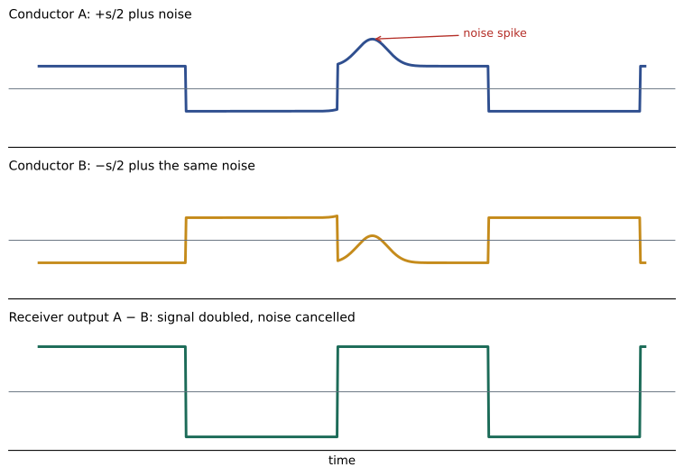
Mathematically, if the transmitter sends \(+s/2\) on one conductor and \(-s/2\) on the other, and noise \(n\) couples onto both, the receiver sees \((s/2 + n) - (-s/2 + n) = s\). The noise disappears. In practice the two conductors are never perfectly identical, so a little common-mode noise is converted to differential-mode noise and leaks through. How well a pair avoids that conversion is called its balance, and it is one of the most important properties of a twisted-pair system.
Why twist the pair?
Balance alone is not enough. Interference from a nearby source is stronger on the conductor closer to the source. If two conductors ran parallel, one would always be a little closer, so the noise would not couple equally and some would get through. Twisting solves this by swapping the positions of the two conductors every half twist. Over each twist, each conductor spends half its time on the near side and half on the far side, so on average both pick up the same noise.
Twisting also helps with magnetic coupling. A changing magnetic field from a power conductor induces a voltage in any loop it passes through. In a twisted pair, each twist forms a small loop, and adjacent loops are wound in opposite directions. The voltages induced in successive loops therefore cancel. The tighter the twist, the smaller the loops and the better the cancellation at high frequencies.
Finally, twisting reduces the pair's own emissions. The equal and opposite currents in the two conductors create magnetic fields that largely cancel at a distance, and the twist makes that cancellation more complete. A well-balanced pair is both a poor antenna for receiving interference and a poor antenna for transmitting it, which helps the cabling system meet electromagnetic compatibility rules.
Twist rates and crosstalk between pairs
A four-pair cable puts four balanced pairs inside one jacket, close together. Each pair is a potential source of interference for the others. If two pairs had the same twist rate, their twists would line up along the cable and the coupling between them would add up instead of cancelling. Manufacturers therefore give each pair a different twist length, often differing by small fractions of a centimetre, so that the twists of neighbouring pairs never stay in step. The specific twist lengths are proprietary and are part of how each manufacturer meets the crosstalk limits for a category.
Higher-category cables add other features to control coupling between pairs and between cables: a cross-shaped spline or separator that holds the pairs apart, tighter and more carefully controlled twists, larger conductors, and in some designs, a jacket shaped or sized to keep neighbouring cables further apart. Category 6A cables are noticeably larger in diameter than Category 5e for this reason, which affects pathway fill, as you will see in RCDD-111.
| Feature | Main purpose |
|---|---|
| Balanced drive and differential receiver | Rejects common-mode noise |
| Twisting each pair | Equalizes coupling onto both conductors and cancels magnetic pickup |
| Different twist rates in each pair | Reduces crosstalk between pairs in the same cable |
| Separator or spline | Holds pairs apart to reduce pair-to-pair coupling |
| Larger cable or special jacket | Increases distance between cables to reduce alien crosstalk |
| Overall foil or braid (screened cables) | Blocks external fields when properly bonded |
Characteristic impedance
A transmission line has a characteristic impedance determined by its geometry and materials: the conductor diameter, the spacing between conductors, and the dielectric constant of the insulation. For a signal travelling down an infinitely long line, the ratio of voltage to current is this impedance. Structured cabling for data is designed to a nominal characteristic impedance of 100 ohms.
Impedance matters because every change along the path, at a connector, a patch cord, a tightly bent section or a place where the pair has been untwisted, presents a slightly different impedance. When a wave reaches an impedance change, part of it is reflected back toward the transmitter. The reflected energy is lost to the forward signal and, in a full-duplex system, it appears as noise at the transmitting end. Return loss, covered in Lesson 4, measures these reflections.
The fraction of voltage reflected at an impedance step is the reflection coefficient, \(\Gamma = (Z_2 - Z_1)/(Z_2 + Z_1)\). A 100 ohm cable connected to a 110 ohm section reflects about 4.8 hundredths of the voltage. Expressed as return loss, that is \(-20 \log_{10}(0.048) \approx 26\) dB. Small mismatches matter at high frequencies because they occur at many points along a channel and their reflections can add up.
Worked problem
Reflection at a mismatch
A patch cord has an impedance of 92 ohms and connects to a 100 ohm permanent link. What is the return loss at the junction from this mismatch alone?
Show solution
- \(\Gamma = (100 - 92)/(100 + 92) = 8/192 \approx 0.0417\).
- \(\text{RL} = -20 \log_{10}(0.0417) \approx 27.6\) dB.
Answer: About 27.6 dB. The larger the return loss, the smaller the reflection.
Balance parameters: TCL and TCTL
Because balance is so important, standards measure it directly. Transverse conversion loss (TCL) measures how much of a common-mode signal applied at one end is converted to a differential-mode signal at the same end. Equal level transverse conversion transfer loss (ELTCTL) measures the same conversion as seen at the far end, adjusted for insertion loss. Larger values mean better balance. These parameters are especially relevant in industrial and electrically noisy environments, and in the MICE environmental classification described in Lesson 9.
Installers can destroy balance without knowing it. Untwisting more of a pair than the connector manufacturer allows, pulling a cable so hard that the twist rate changes, crushing it with over-tightened ties, or bending it tighter than its minimum bend radius all make the two conductors less alike. The cable may still pass a basic continuity test, but its balance, crosstalk and return loss suffer, and noise rejection drops.
Power over the same pairs
Balanced pairs have another useful property: a DC voltage can be applied between two pairs, using the centre taps of the transformers at each end, without disturbing the differential data signal. This is how Power over Ethernet works. The power current flows equally on both conductors of a pair, so it looks like a common-mode signal to the data receiver. IEEE 802.3bt allows up to about 90 W at the power sourcing equipment using all four pairs.
Power over Ethernet depends on balance in a new way. If the two conductors of a pair have different resistances, the DC current divides unequally and can saturate the transformer, distorting the data signal. Standards therefore limit DC resistance unbalance within a pair and between pairs. The current also heats the cable, raising insertion loss, which is why large bundles carrying high-power PoE need attention to bundle size and pathway ventilation. You will return to this in RCDD-112.
Back in the ceiling
Roz shows Daniel how to think about Priya's feeders. A well-installed Category 6A cable, terminated with its twists preserved and run at a sensible distance from the feeders, will reject most of the low-frequency magnetic field from them because the field couples nearly equally into both conductors of every pair. The risk rises where cables run parallel and very close to high-current conductors for long distances, near variable-frequency drives that produce fast switching edges, or where installation has damaged the balance. Those are the places the design will address with separation, pathway choice and, in a few areas, screened cabling. That analysis is the subject of Lessons 9 to 11.
Exam focus: connecting balance to everything else
Balance links several topics that the exam may test separately. Good balance keeps external interference in common mode, where the receiver rejects it; it also keeps the cable's own emissions low, which helps equipment meet EMC rules; it keeps Power over Ethernet current evenly divided; and it supports the crosstalk and return loss performance that the certification tester measures. When a question asks why a particular installation practice matters, such as limiting pair untwist, preserving bend radius or avoiding crushed cable, the underlying answer is usually that the practice preserves balance and impedance.
Two further points are often confused. First, balance does not depend on a shield. An unscreened cable can be very well balanced, and a screened cable can be poorly balanced. Second, impedance is not the same as resistance. A long 100 ohm cable does not have 100 ohms of DC resistance; its DC loop resistance is a few ohms, while its characteristic impedance, set by its geometry, is 100 ohms at all lengths.
Worked problem
Voltage across a balanced pair
A transmitter drives a pair with \(+0.5\) V on one conductor and \(-0.5\) V on the other. A nearby source induces \(+0.3\) V on the first conductor and \(+0.28\) V on the second, because the pair is slightly unbalanced at that point. What differential voltage does the receiver see, and how much of it is noise?
Show solution
- Conductor A: \(0.5 + 0.3 = 0.8\) V. Conductor B: \(-0.5 + 0.28 = -0.22\) V.
- Difference: \(0.8 - (-0.22) = 1.02\) V.
- The wanted signal is 1.0 V, so 0.02 V of the 0.3 V common-mode noise has leaked through.
Answer: The receiver sees 1.02 V, of which 0.02 V is noise. Perfect balance would have removed all of it; the small difference in coupling converted a little common-mode noise into differential noise.
Common mistakes
MistakeThinking twisting is mainly for mechanical strength.
InsteadTwisting equalizes coupling onto both conductors and cancels magnetic pickup. It is an electrical design feature.
MistakeAssuming common-mode noise never reaches the receiver.
InsteadImperfect balance converts some common-mode noise to differential noise. TCL and ELTCTL measure how much.
MistakeTreating impedance as the same thing as DC resistance.
InsteadCharacteristic impedance is set by geometry and dielectric and governs reflections. DC resistance is the resistance of the copper.
MistakeIgnoring PoE effects on balance.
InsteadDC resistance unbalance can disturb the data signal when power is applied, so standards limit it.
Summary and key terms
- A balanced pair carries equal and opposite signals and the receiver measures only the difference, rejecting common-mode noise.
- Twisting equalizes coupling onto both conductors and cancels magnetic pickup; different twist rates reduce crosstalk between pairs.
- Structured data cabling is designed to a nominal 100 ohm characteristic impedance; mismatches cause reflections measured as return loss.
- TCL and ELTCTL measure balance; poor installation practice degrades balance even when continuity is fine.
- Power over Ethernet uses the pairs as a common-mode path, which makes resistance unbalance and heating design concerns.
- Balanced transmission
- Sending a signal as equal and opposite voltages on two matched conductors and detecting the difference.
- Differential mode
- The signal that appears as a difference between two conductors.
- Common mode
- A signal or noise that appears equally on both conductors with respect to ground.
- Characteristic impedance
- The ratio of voltage to current for a wave travelling on a long transmission line, set by its geometry and materials.
- Transverse conversion loss (TCL)
- A measure of how much common-mode signal is converted to differential mode, indicating balance.
- Reflection coefficient
- The fraction of an incident voltage wave that is reflected at an impedance change.
Practice problems
Work each problem on paper first, then reveal the answer to check.
A 100 ohm line meets a 120 ohm section. What is the reflection coefficient?
Show answer
\(\Gamma = (120 - 100)/(120 + 100) = 0.091\).
Why do the four pairs in a cable have different twist lengths?
Show answer
So their twists do not line up along the cable, which would make coupling between pairs add up rather than cancel.
Why can PoE share the data pairs?
Show answer
The power is applied between pairs through transformer centre taps, so it flows equally on both conductors of each pair and appears as common mode to the data receiver.
Lesson quiz · 5 questions
Score 60% or more to complete this lesson.
Create a free account to save your progress, take quizzes and earn a certificate.