
RCDD-110 · Lesson 10 of 12 · 20 min
Separation from power and noise sources
▶ Video coming soon A video version of this lesson is on the way.
At the second coordination meeting, Priya's electrical layout and Daniel's cable tray routes collide on the third floor. A 400 A feeder in a cable tray and the main ICT cable tray both want the same narrow corridor ceiling for about 30 m. Marcus Feld wants a decision before the ceiling contractor starts. Priya points out that the code only requires a small clearance between communications cables and power conductors in most situations. Daniel knows the code minimum is only part of the story. Roz asks him to explain to the room why ICT designers ask for more, and what they actually need.
Separation between ICT cabling and electrical power or other noise sources serves two different purposes. The first is safety: keeping communications circuits, which people touch every day, from being energized by a fault in a power circuit. Electrical codes set minimum separation for safety. The second is performance: keeping interference from power circuits and equipment from degrading the signals. Cabling and installation standards give guidance for performance separation. The two are often confused, and a designer needs to be clear which one a requirement serves.
Safety separation in the electrical code
The Canadian Electrical Code, Section 60, requires communication conductors to be kept separate from conductors of electric light, power and Class 1 circuits, with specific clearances and with relaxations where the circuits are separated by barriers, raceways or suitable cable types. Check the rule in the edition your jurisdiction has adopted for the exact distances and exceptions.
These safety rules are minimums. They prevent a failure of power cable insulation from directly contacting communications conductors and putting a dangerous voltage on telephone handsets, network equipment and the people using them. They are written for safety, not signal quality, and the code does not claim that a code-compliant separation will prevent interference. The authority having jurisdiction enforces code rules; performance guidance is enforced only if the designer writes it into the specification.
Performance separation
Interference from power circuits depends on the coupling mechanisms from Lesson 9. At power frequencies and their harmonics, the main mechanism is magnetic coupling from current flowing in power conductors. The field around a single conductor falls with distance, and it is much smaller when the phase and neutral conductors of a circuit run close together, because their opposing currents cancel most of the field. At higher frequencies, fast switching in drives, power supplies and lighting adds capacitive coupling and radiated energy.
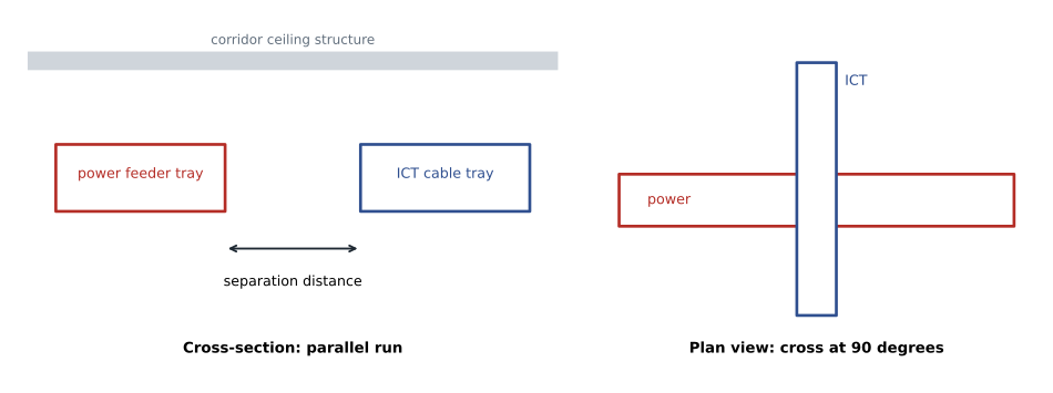
So the factors that determine how much separation is needed are: the current and voltage of the power circuit, whether its conductors are grouped together (as in a cable) or spread out (as in single conductors in a tray), whether the power cable is screened or in a metal raceway, the type of ICT cable and how well it is balanced or screened, whether the ICT cable is in a metal pathway, and the length over which the two run in parallel. A short crossing at right angles causes very little coupling; a long parallel run causes much more.
How standards approach it
North American and international standards have taken different approaches over the years. Older editions of the TIA pathways and spaces standard gave a table of separation distances based on the power circuit's rating and whether metal pathways were used. Current TIA documents give more general guidance and refer to the performance of the installed cabling, recognizing that balanced cabling designed to current categories is much more resistant to interference than the cabling of the 1990s. Many designers still use the older tables, or owner design standards derived from them, as a conservative starting point.
International practice, in ISO/IEC 14763-2 and the related European standard EN 50174-2, calculates a minimum separation from a classification of the ICT cable and the pathway. Each ICT cable is placed in a segregation class according to how well it resists coupling, based on its screening and balance. Each pathway type, open tray, perforated metal tray or solid metal trunking with a lid, gets a factor that reduces the required distance. The result is multiplied for the number of power circuits. The method recognizes that well-balanced or screened cables in closed metal pathways can run much closer to power than unscreened cables in open trays.
| Condition (example design standard) | Example minimum separation |
|---|---|
| ICT cable crossing power at right angles | Cross at 90 degrees; keep as short as practical |
| ICT tray parallel to branch circuit cables in metal raceway | 100 mm |
| ICT tray parallel to open single-conductor feeders | 300 mm or more, increase for long runs |
| ICT cabling and fluorescent or LED light fixtures | 125 mm |
| ICT cabling and motors, transformers, drives | 1,000 mm or more, or route around the room |
| Telecommunications room and electrical transformer | Not on a shared wall; separate rooms |
The table is an example, not a requirement from a single standard. Its purpose is to show the kind of distances designers use: tens of centimetres from ordinary power wiring, more from high-current feeders, and a metre or more from motors, transformers and drives. Where a project has its own design standard, follow it. Where none exists, the RCDD writes one into the design basis, explains its source and applies it consistently.
Metal pathways and barriers
Metal pathways help in two ways. A closed steel conduit or trunking around either the power or the ICT cables reduces both capacitive and magnetic coupling, steel being particularly effective against low-frequency magnetic fields. A metal barrier or divider in a shared tray, when properly bonded, creates a separate compartment that can satisfy both the code's barrier requirement and much of the performance concern. Metal pathways must be continuous and bonded along their length to work. A gap or an unbonded section of tray reduces their effectiveness and may create safety issues.
Aluminium and non-ferrous pathways block electric fields and high-frequency fields well but have little effect on low-frequency magnetic fields. Non-metallic pathways provide physical separation but no shielding. These differences are why separation guidance often gives different values for open, non-metallic and closed metal pathways.
Power over Ethernet and power-limited circuits
Power over Ethernet cables carry power, but they are power-limited, balanced circuits that run in the same cables as data. They do not need separation from other ICT cables for safety. The main concern with PoE is heat in large bundles, covered in RCDD-112. Low-voltage DC power distribution systems for lighting and other building services, which may be installed in the same ceiling space, have their own code classification and separation requirements, and the RCDD must coordinate with the electrical engineer on which circuits can share pathways with ICT cabling.
Spaces as well as pathways
Separation applies to rooms too. Telecommunications rooms and equipment rooms should not share walls with electrical rooms containing transformers or switchgear, and should not be located next to elevator machine rooms, large mechanical equipment or other strong sources of magnetic fields. Where this cannot be avoided, the designer considers increased distance between racks and the shared wall, magnetic shielding in rare cases, or relocation. RCDD-111 covers the location of spaces in more detail.
Worked problem
How much does distance help?
The magnetic field from a long single conductor falls roughly as \(1/r\). If the field from a feeder is a certain value 100 mm from the conductor, how much weaker is it at 300 mm and at 600 mm, in decibels?
Show solution
- At 300 mm the field is one third as strong: \(20 \log_{10}(1/3) \approx -9.5\) dB.
- At 600 mm it is one sixth as strong: \(20 \log_{10}(1/6) \approx -15.6\) dB.
Answer: About 9.5 dB weaker at 300 mm and 15.6 dB weaker at 600 mm. For a tightly grouped circuit cable the field falls faster, roughly as one over the distance squared, so distance helps even more.
Resolving the third-floor clash
Daniel presents three options to the meeting. Option one moves the ICT tray to the opposite side of the corridor, about 600 mm from the feeder tray, and crosses the feeder at right angles where the tray turns into the telecommunications room. Option two keeps the trays side by side but puts a bonded steel barrier between them and runs the ICT tray at a different elevation. Option three asks Priya whether the feeder could be installed as a multi-conductor armoured cable rather than single conductors in tray, which would greatly reduce its external magnetic field. Priya says the feeder will be in a multi-conductor cable anyway, which settles most of the concern, and Marcus prefers option one because it is simplest for the ceiling contractor. The design records the decision, the code clearance it exceeds and the project separation standard it meets.
Separation inside equipment rooms and racks
Separation also applies inside telecommunications and equipment rooms. Power distribution units, power cords and ICT patch cords share the same racks and cabinets. Good practice routes power on one side of a rack and data on the other, uses separate vertical managers for power and data where possible, and keeps power cords from being bundled with patch cords. Overhead power busways in data rooms should be separated from overhead cable trays, usually by putting them at different elevations, and where they must cross they should cross at right angles.
Uninterruptible power supplies, transformers in power distribution units and large battery systems are strong local sources of magnetic fields. Placing them at the end of a row, away from patch fields, avoids most problems. These details are part of the space planning covered in RCDD-111 and the power topics in RCDD-113.
Exam focus: safety versus performance
Exam questions about separation often turn on whether a requirement is a code rule or a performance recommendation. If the question asks what is required to prevent a power fault from energizing communications circuits, or whether two cables may share a box or raceway, the answer comes from the electrical code. If it asks how to reduce interference or how far to keep cabling from fluorescent lighting, motors or transformers, the answer comes from design guidance. Also remember that a barrier in a shared raceway or tray must be fixed and continuous, and that the code's exceptions usually depend on the power conductors being enclosed in a raceway or suitable metal-sheathed cable.
Worked problem
Choosing the requirement
An installer wants to run a Category 6A cable through the same junction box as a 120 V lighting circuit to save a box. Is this a performance question or a safety question, and what is the answer?
Show solution
- Sharing a box with power conductors is a code question, because it concerns safety from power faults.
- The code does not allow communications and power conductors to share a box unless a permanent barrier separates them, with limited exceptions for power supplying the communications equipment itself.
Answer: It is a safety question. Without a listed barrier, the cable must use its own box.
Whatever the source of a separation rule, the designer's job is to show it on the drawings and write it into the specification, so that installers and inspectors know what is expected and where.
Common mistakes
MistakeTreating the code clearance as a performance guarantee.
InsteadCode separation is for safety. It does not claim to prevent interference; performance separation needs its own design rule.
MistakeAssuming any metal pathway shields magnetic fields.
InsteadSteel is effective against low-frequency magnetic fields; aluminium is not. Continuity and bonding also matter.
MistakeRunning ICT cabling parallel to power for long distances to save tray.
InsteadCoupling grows with parallel length. Cross at right angles and separate parallel runs.
MistakeLocating telecommunications rooms next to electrical rooms with transformers.
InsteadTransformers produce strong magnetic fields; keep ICT spaces away from them.
Summary and key terms
- Separation serves safety, set by the electrical code, and performance, set by design guidance and owner standards.
- Code rules prohibit sharing raceways and boxes without barriers and require minimum clearances, with exceptions for raceways, armoured cable and barriers.
- Performance separation depends on circuit current, conductor grouping, pathway type, ICT cable type and length of parallel run.
- International practice classifies ICT cables and pathways to calculate separation; many North American projects use owner design tables.
- Steel pathways and barriers, crossings at right angles and careful location of ICT spaces reduce coupling.
- Safety separation
- Separation required by electrical codes to keep power faults from energizing communications circuits.
- Performance separation
- Separation chosen to limit interference from power circuits and equipment.
- Segregation class
- A rating of an ICT cable's resistance to coupling, used to calculate separation in international standards.
- Barrier
- A fixed, continuous partition in a raceway or tray that separates power and communications conductors.
- Parallel run
- A section where ICT and power cables follow the same route side by side.
Practice problems
Work each problem on paper first, then reveal the answer to check.
Why does a multi-conductor power cable produce less external magnetic field than single conductors spread in a tray?
Show answer
The opposing currents in the closely grouped phase and neutral conductors cancel most of each other's field.
Which is more effective against a 60 Hz magnetic field: an aluminium tray or a steel conduit?
Show answer
A steel conduit, because steel is magnetic and diverts low-frequency magnetic fields.
Why cross power at right angles?
Show answer
The coupling length is minimized and the magnetic field lines are oriented to induce little voltage in the ICT cable.
Lesson quiz · 5 questions
Score 60% or more to complete this lesson.
Create a free account to save your progress, take quizzes and earn a certificate.