
PWR-520 · Lesson 2 of 12 · 22 min
Advanced turbine and generator topics
▶ Video coming soon A video version of this lesson is on the way.
Keswold's two generators are air-cooled, totally enclosed machines with air-to-water coolers, and its steam turbine is a single-casing extraction condensing unit of 18 MW (PWR-320). The First Class syllabus, however, assumes that a chief engineer may one day run a plant with much larger machines. Anselm had started his career, before the mill, as a junior operator at a utility station with hydrogen-cooled generators, and Morwenna asked him to teach that part of the session. "You've done it," she said. "I've only read about it at the size you ran." She took the second half: what a chief needs to know about the condition of a turbine-generator and the long-term agreements that pay for keeping it healthy.
This lesson covers the cooling of large generators by hydrogen and water, the seal oil and gas systems that hydrogen cooling requires, stator cooling water chemistry, the condition monitoring methods used on turbine-generators, the main life-limiting mechanisms of large steam turbines, and how inspection intervals and long-term service agreements are set. Two worked examples show why hydrogen purity matters and how a hydrogen leak rate is estimated.
Why large generators use hydrogen
Generator losses, in the copper of the windings, the iron of the core and the friction of the rotor in its cooling gas, all end up as heat that the cooling system must remove. Losses grow with output, and the active parts of a larger machine have less surface per unit of volume, so above roughly 100 to 300 MVA (typical) air cooling becomes impractical. Hydrogen has about seven times the thermal conductivity of air and about one fourteenth of its density. It carries heat away far better, and the windage and fan losses of the rotor spinning in the gas, which are roughly proportional to the gas density, fall dramatically. Raising the hydrogen pressure to several hundred kilopascals increases its heat-carrying capacity further, at the cost of higher windage. Hydrogen is also chemically inert towards the insulation, which lasts longer without oxygen and the ozone of partial discharges in air.
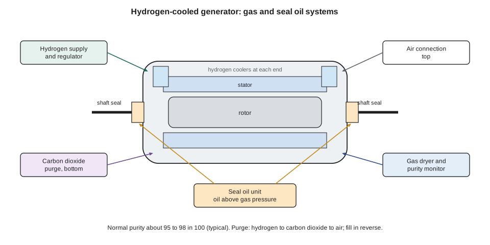
The disadvantage is that hydrogen mixed with air between about 4 and 75 in 100 by volume is flammable and can explode. A hydrogen-cooled generator is therefore a gas-tight pressure enclosure, its shaft seals are fed with oil at a pressure just above the gas pressure, its purity is monitored continuously, and it is filled and emptied through an inert gas, usually carbon dioxide, so that air and hydrogen never mix inside it.
- Purity is kept typically above about 95 to 98 in 100 hydrogen (typical; follow the manufacturer). Air leaks in with the seal oil and through the casing, and the purity falls slowly; operators scavenge by venting a little gas and adding fresh hydrogen.
- Pressure is held by a regulator from the hydrogen supply; a falling pressure with steady temperature means a leak, and the makeup rate is logged daily.
- Dew point is kept low by a gas dryer; moisture in the gas reduces insulation resistance and can lead to stress corrosion cracking of retaining rings on older machines.
- Purging: to open the machine, the hydrogen is displaced by carbon dioxide from the bottom, the carbon dioxide is then displaced by air from the top, with purity analysers confirming each step. Filling reverses the process. Carbon dioxide is used because it is heavier than both air and hydrogen and is not flammable.
Worked problem
Why purity matters
A large generator has windage and fan losses of about 400 kW with hydrogen at 98 in 100 purity, the rest being air. Taking windage as proportional to gas density at constant pressure and temperature, estimate the losses if purity falls to 95 in 100. Use molar masses of 2.016 for hydrogen and 28.97 for air.
Show solution
- \[\frac{\rho_{98}}{\rho_{air}} = \frac{0.98 \times 2.016 + 0.02 \times 28.97}{28.97} = 0.0882 \qquad \frac{\rho_{95}}{\rho_{air}} = \frac{0.95 \times 2.016 + 0.05 \times 28.97}{28.97} = 0.1161\]
- \[P_{95} = 400 \times \frac{0.1161}{0.0882} = 527 \text{ kW}\]
Answer: A drop of only three points in purity raises the gas density by about a third and adds about 127 kW of losses, which is lost output and extra heat for the hydrogen coolers to remove. Over a year at full load that is more than a million kilowatt-hours. Purity is watched for economic as well as safety reasons, and a steady fall in purity points to increased air ingress, often through the seal oil system.
Seal oil systems
The shaft of a hydrogen-cooled generator passes through the casing at both ends, and gas must be kept in while the shaft turns. Seal rings ride on the shaft in a housing, and oil is fed between the rings at a pressure typically about 35 to 85 kPa (5 to 12 psi) above the gas pressure (typical). The oil flows outward along the shaft on both the air and hydrogen sides and is drained away, so gas cannot escape. The oil that flows to the hydrogen side absorbs hydrogen and the oil on the air side absorbs air, so many designs keep the two flows separate and treat the oil in a vacuum degasifier before it returns, to avoid carrying air into the machine and lowering purity.
The seal oil system has a main pump, a standby pump and an emergency pump on direct current, and a differential pressure regulator that tracks the gas pressure. Loss of seal oil differential is an emergency: without it hydrogen escapes along the shaft into the turbine hall, where it can ignite. Operators who have run these units, as Anselm had, learn to watch the seal oil differential and the hydrogen makeup together; a rising makeup rate with a falling differential tells its own story. Oil that reaches the inside of the generator, from a seal oil upset or a flooded drain, degrades insulation and must be cleaned out at the next opportunity.
Worked problem
Estimating a hydrogen leak
A generator has a gas volume of 60 m³. With the hydrogen supply valved off for a 24-hour leak test, its pressure falls from 400 kPa gauge to 385 kPa gauge at a steady gas temperature of 40 °C. Atmospheric pressure is 101.3 kPa. Estimate the leakage in normal cubic metres per day (0 °C and 101.325 kPa).
Show solution
- \[V_{N} = V \times \frac{P_1 - P_2}{P_N} \times \frac{T_N}{T} = 60 \times \frac{501.3 - 486.3}{101.325} \times \frac{273.15}{313.15} = 7.75 \text{ m}^3\text{/day}\]
Answer: The result is compared with the manufacturer's allowable leakage for the machine and with the plant's trend. Temperature must be held steady or corrected for, because a small change in gas temperature changes the pressure as much as a significant leak. A test that shows a rising leakage rate leads to a search with a hydrogen detector around the seals, the bushings, the cooler connections and the gas piping.
Water-cooled stator windings
In the largest generators, hydrogen alone cannot remove the heat from the stator bars, and the bars are built with hollow copper strands through which stator cooling water flows. The water must be extremely pure, because it is in direct contact with conductors at the full generator voltage: its conductivity is held very low, typically below about 0.5 µS/cm (typical), by a continuous bypass through a mixed-bed ion exchanger. Its chemistry is also chosen to protect the copper. Some systems run with high dissolved oxygen and others with very low oxygen; in between, at intermediate oxygen levels, copper oxide forms and moves around the circuit, depositing in the narrow strands and blocking flow. A blocked strand overheats its bar, and the result can be insulation failure and a forced outage lasting months.
Stator cooling water leaks are another hazard. Water leaking from a bar connection into the hydrogen space wets the insulation; hydrogen leaking into the water circuit shows up as gas in the water tank. Monitoring therefore includes water flow and pressure drop across the winding, conductivity, dissolved oxygen, the temperature of each bar outlet, and gas in the water. A slowly rising pressure drop or diverging bar temperatures point to blockage long before a failure.
Condition monitoring of turbine-generators
A chief engineer cannot open a turbine to see how it is, so the plant relies on measurements that reveal the condition of the machine while it runs. PWR-320 introduced vibration monitoring and the 1X rise at Keswold's bearing 3 on November 13. A full program combines several methods.
- Vibration: shaft relative vibration by proximity probes, casing vibration, phase and orbit plots, and transient data during startups and shutdowns, which show critical speeds, rubs, misalignment and cracks.
- Thermal performance: first-stage pressure, stage pressures and temperatures, and section efficiencies trended over time show deposits and wear (PWR-330, PWR-410). Keswold's first-stage pressure trend has been flat for two years.
- Lubricating oil analysis: viscosity, acid number, water, particle counts, varnish potential and wear metals give early warning of bearing wear, contamination and oil degradation.
- Generator electrical monitoring: partial discharge measurements show insulation deterioration in the stator winding; rotor flux probes detect shorted turns in the field winding; a generator condition monitor detects particles from overheating insulation in hydrogen-cooled machines.
- Thermography of bushings, connections and cables, and dissolved gas analysis of transformer oil, find hot spots and internal faults before they fail.
- Borescope inspections of gas turbines through ports in the casing, as at Keswold's outage on October 7 (PWR-320), reveal coating loss, cracking and foreign object damage without disassembly.
The value of the data lies in trends and baselines. Ingeborg keeps a baseline for every measurement taken after the fall outage, and alarm limits are set from that baseline as well as from the absolute limits in the manufacturer's guidance and in ISO 20816. A change that is still inside absolute limits but well outside the machine's normal scatter, like bearing 3's 1X rise, deserves attention.
Life-limiting mechanisms in large steam turbines
Large utility steam turbines run for decades, and their lives are limited by a handful of mechanisms that a chief engineer must understand, because they decide inspection intervals and repair budgets.
- Creep of the high-temperature rotor and casings, especially at the inlet of the high pressure and reheat turbines (PWR-510's Larson-Miller relation applies to rotors as well as tubes).
- Low-cycle thermal fatigue from startups and load changes, which cracks rotor surfaces at grooves and radii where the temperature changes fastest; fast starts consume life, which is why starting procedures limit the rate of metal temperature change (PWR-320).
- High-cycle fatigue of blades from vibration, often triggered by a resonance, erosion, deposits or a change in operating conditions.
- Solid particle erosion of the first stages by oxide scale from the boiler, and water droplet erosion of the last stage blades of the low pressure turbine.
- Stress corrosion cracking of low pressure discs and blade attachments, where steam first condenses in the Wilson zone and impurities concentrate, as PWR-330 explained.
- Embrittlement of older rotor steels after long service at intermediate temperatures, which lowers their resistance to brittle fracture at low temperatures, so warming before full speed matters.
Turbine manufacturers and insurers recommend major inspection intervals in equivalent operating hours, in which each start is counted as a number of hours of operation, because a turbine that cycles daily ages differently from one that runs steadily. A unit with 6,000 operating hours and 300 starts may be due for inspection before one with 8,000 hours and 20 starts, depending on the weighting the manufacturer uses.
Long-term service agreements and the chief's role
Keswold's gas turbine is maintained under a long-term service agreement (LTSA) with its manufacturer (PWR-420). The manufacturer supplies parts, field engineers and repairs for scheduled inspections, and in return is paid a fee based on fired hours or starts, often with guarantees for availability and performance. An LTSA moves some of the technical risk to the manufacturer and gives the plant access to the fleet's experience and parts pool; it also ties the plant to one supplier, can be expensive, and leaves the plant's own staff with less hands-on knowledge of the machine.
A chief engineer manages the LTSA rather than handing the machine over to it. That means understanding how the fee is calculated, how starts, trips and fuel changes affect it, what the agreement says about operation outside the manufacturer's limits, what data the manufacturer receives through remote monitoring, and how the plant's own observations are recorded and passed on. Morwenna keeps a short register of every LTSA clause that limits how Keswold may operate the machine, and she reviews it before any change to operating practice, such as more frequent cycling or a higher hydrogen content in the fuel gas.
Common mistakes
MistakeLetting hydrogen purity drift down because the generator still runs.
InsteadLow purity raises windage losses and can signal air ingress; scavenge and find the cause.
MistakeOpening a hydrogen-cooled generator without the carbon dioxide step.
InsteadAlways purge hydrogen with carbon dioxide before admitting air, and confirm each step with the analyser.
MistakeIgnoring a slow rise in hydrogen makeup.
InsteadTrend makeup and seal oil differential together, and do a temperature-corrected leak test.
MistakeWatching stator cooling water conductivity but not its oxygen.
InsteadIntermediate oxygen levels release copper oxide that blocks strands; follow the oxygen regime the design calls for.
MistakeJudging vibration only against absolute limits.
InsteadCompare against the machine's own baseline; a large change inside the limits deserves investigation.
MistakeLeaving the LTSA to the manufacturer.
InsteadKnow the clauses that limit operation and how operating changes affect fees and guarantees.
Summary and key terms
- Hydrogen cools large generators far better than air and cuts windage losses, but needs a gas-tight casing, seal oil, purity monitoring and carbon dioxide purging.
- Purity affects losses: a fall from 98 to 95 in 100 raises gas density by about a third.
- Leak rates are found from temperature-corrected pressure decay and compared with the manufacturer's allowance and the trend.
- Water-cooled stators need very low conductivity and the correct oxygen regime to avoid copper oxide blockage of strands.
- Condition monitoring combines vibration, thermal performance, oil analysis, partial discharge, thermography, dissolved gas analysis and borescope inspection, judged against baselines.
- Creep, thermal fatigue, blade fatigue, erosion, stress corrosion cracking and embrittlement limit turbine life; inspections are scheduled in equivalent operating hours.
- A chief engineer manages a long-term service agreement actively, knowing how operation affects its fees, guarantees and limits.
- Windage loss
- Power lost to friction between a rotor and the gas surrounding it.
- Seal oil
- Oil supplied to generator shaft seals at a pressure above the gas pressure to keep hydrogen in.
- Scavenging
- Venting some generator gas and adding fresh hydrogen to restore purity.
- Stator cooling water
- High-purity water circulated through hollow conductors in a large generator stator.
- Partial discharge
- Small electrical discharges within insulation that indicate its deterioration.
- Equivalent operating hours
- A measure of turbine ageing that counts starts and trips as additional hours.
- Long-term service agreement
- A contract with a manufacturer for parts, repairs and inspections over many years.
Practice problems
Work each problem on paper first, then reveal the answer to check.
Relative density of 97 in 100 hydrogen (rest air) compared with air?
Show answer
About 0.0975.
A 50 m³ generator loses 10 kPa in 24 h at 35 °C. Leakage in normal m³/day?
Show answer
About 4.4 m³/day.
Why is carbon dioxide used as the purge gas?
Show answer
It is inert and heavier than both air and hydrogen, so it separates them cleanly.
Name two mechanisms that limit a steam turbine rotor's life.
Show answer
Creep and low-cycle thermal fatigue (also embrittlement or stress corrosion cracking).
Lesson quiz · 5 questions
Score 60% or more to complete this lesson.
Create a free account to save your progress, take quizzes and earn a certificate.