
IRW-230 · Lesson 6 of 12 · 24 min
Shear studs and composite floors
▶ Video coming soon A video version of this lesson is on the way.
On Wednesday, November 11, Shay spent the day on the second floor at Ashcroft with Femi Ogunleye, the deck crew's stud welder. Femi had a stud gun the size of a large drill, a cable as thick as a wrist running down to a welding power source on the ground, a cart of boxes of studs and a box of ceramic ferrules, and a chalk line. Before welding a single production stud, he welded two studs on a scrap of beam the general contractor had left for the purpose, then took a length of pipe, slid it over each stud and bent it well over to one side. Neither stud cracked at its base. "Now the machine's set and I know the steel's clean," he said. "Now we can start."
Shear studs are the steel pins that turn a steel beam and a concrete slab into one composite floor. They are simple pieces of steel, but each one is part of the floor's strength, and welding them well takes skill, the right settings and steady checking. This lesson explains how composite floors work, what shear studs are, how they are laid out and welded, how they are tested, and what happens between the studs and the concrete pour.
How a composite floor works
A steel beam with a concrete slab on top of it carries load. If the slab just rests on the beam, the two bend separately, the slab sliding on the beam's top flange, and each carries part of the load on its own. If the slab is locked to the beam so it cannot slide, the beam and slab bend together as one deeper member. The concrete above takes compression, the steel below takes tension, and the combined section is much stiffer and stronger than the two parts acting separately. That is composite action, and it lets a designer use lighter beams for the same floor.
The lock between slab and beam is the row of shear studs welded to the top flange. When the floor bends, the slab tries to slide along the beam, and the studs, embedded in the concrete, resist that slip by shear. The deck's embossments do a similar job between the slab and the deck, so the deck acts as bottom reinforcement for the slab between beams.
Shear studs
A shear stud, or headed stud anchor, is a round steel bar with a forged head at one end and a flux load at the other. Common diameters are 19 mm (3/4 in) and 22 mm (7/8 in). Studs are delivered in boxes by diameter and length, with ceramic ferrules, small rings that fit around the base of the stud during welding to hold the molten metal and shield it. The length before welding is a little longer than after, because the stud burns off a few millimetres as it is welded.
The designer shows the number of studs on each beam, their size and their spacing, often as a number in the beam's label on the framing plan, such as (24) for twenty-four studs. On composite deck, studs go in the ribs that run over the beam, so their spacing is a multiple of the rib spacing. Where a beam needs many studs, they go in pairs, side by side in each rib, or the designer may call for studs in every rib and in two rows.
Worked problem
Checking stud height and cover
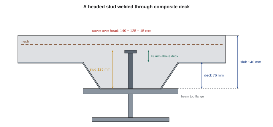
At Ashcroft the deck is 76 mm deep, the studs are 125 mm long after welding, and the slab is 140 mm thick measured from the bottom of the deck. Does each stud project at least 38 mm above the top of the deck, and is there at least 13 mm of concrete over the head?
Show solution
- Projection above the deck = 125 − 76 = 49 mm, more than 38 mm.
- Cover over the head = 140 − 125 = 15 mm, more than 13 mm.
Answer: Both checks pass. These are typical minimums from the steel design standards; the drawings give the job's values, and a stud that comes out short after welding can fail the projection check.
When studs go on
Studs are installed only after the deck is down and fastened, using the deck as the working surface. Studs sticking up from bare beam flanges are a tripping hazard for connectors walking the steel, so Crossbeam never has studs shop-welded to beams on its jobs unless the erection plan provides for safe access, and Ontario's general rules about keeping work surfaces free of tripping hazards apply.
Stud welding
Most studs on composite floors are welded through the deck. The welder sets a stud and ferrule in the gun, places the gun on the deck over the beam, and pulls the trigger. The gun lifts the stud slightly, draws an arc that melts the stud's end and a pool in the deck and flange, then plunges the stud into the pool. The whole weld takes less than a second. When the ferrule is knocked off, a good weld shows a full ring of weld metal, called the flash or fillet, all the way around the base of the stud.
- The power source must be large enough for the stud diameter, the cable runs as short as practical, and the ground clamp is fixed solidly to the steel close to the work, because a poor ground gives poor welds.
- The deck must be tight to the beam flange where each stud goes, clean and dry, without heavy galvanizing build-up, oil, water or rust. Through-deck welding works only up to a certain deck thickness and coating weight, which the stud maker and the standard state.
- Settings, the current and the weld time, are set for the stud size, deck and position and confirmed by the pre-production test.
- Studs are laid out with a chalk line along the beam centreline, which the welder finds by marking the beam's position on the deck from below or from the column lines, because a stud that misses the flange is welded only to the deck.
Stud welding in Canada follows CSA W59 and is done by a CWB-certified company with qualified stud welders. Femi holds Crossbeam's stud welding qualification.
Testing studs
Stud welds are tested by bending, because a good stud weld is stronger than the stud. The codes set out the tests in detail; the common pattern is this.
- Pre-production test. At the start of each production period, and whenever the settings, the equipment, the deck or the position change, the first studs are welded on a test plate or on the job, as the code allows, and bent about 30 degrees from vertical. If they bend without the weld cracking, production may start; if not, settings are adjusted and the test repeated.
- Visual inspection. Every stud is looked at after its ferrule is knocked off. A stud without a full 360-degree flash, or one that is short, crooked or undercut, is suspect.
- Bend test of suspect studs. A suspect stud is bent about 15 degrees toward the missing part of the flash. If its weld cracks, the stud is replaced. Studs bent in testing and passed are left bent; they will be buried in concrete.
- Hammer test. Some inspectors also strike studs with a hammer; a stud that rings dully, or moves, is bent tested.
The inspector, or the general contractor's testing agency, may also bend a sample of studs on each beam. Failed studs are replaced with a new stud welded beside them, or by fillet-welding a stud, as the code allows.
Ashcroft's studs
Worked problem
How many studs on a floor?
Ashcroft's floor beams like B2-14 are 9.1 m long, and the deck ribs over them are at 305 mm. The drawings call for one stud in every rib over the beam except the first and last rib at each end. How many ribs cross the beam, and how many studs does it get?
Show solution
- Rib spaces = 9,100 ÷ 305 ≈ 29.8, so 29 full ribs land on the beam between its ends.
- Leave out the first and last rib: 29 − 2 = 27 studs.
Answer: 27 studs, which matches the (27) on the framing plan for B2-14. Femi counted the ribs on the deck before he snapped his line, and checked his count against the label.
Femi welded the Ashcroft studs from November 2 to 12, working floor by floor behind the deck crew's final fastening, and the testing agency's inspector checked them on November 12. One beam on the second floor had four studs with incomplete flash at its north end, where the deck had not been tight to the flange. Femi bend-tested them; two cracked, and he welded replacements. The cause was a deck sheet that had sprung up between two support welds, and Ilona had the deck crew add a weld before the stud welding continued along that line.
From studs to the pour
After the studs are welded and inspected, the floor is ready for the trades that follow. The rod gang places welded wire reinforcement or bars on the deck, the pour stops at the edges and openings are checked for height and tied back, and the general contractor inspects the deck before concrete. At Ashcroft, Tobias's rod gang was scheduled to lay the mesh from November 16 to 20 and the concrete pours were planned for late November.
Before the pour, the deck is cleaned of stud ferrules, banding, screws and debris, which must not end up in the concrete. Any shoring the deck layout calls for under long deck spans is set. Concrete is placed in a way that does not overload the deck: it is not dumped in a pile in mid-span, and buggies or pump lines are kept on planks or near supports.
Safety with stud welding
Stud welding uses high current, typically hundreds to more than a thousand amps for a fraction of a second, and its cables are heavy and lie across the deck where people walk. The welder wears eye protection with the right shade, gloves and flame-resistant clothing, and others nearby avoid looking at the arc. Cables are routed so they do not cross open edges or walkways where possible and are inspected for damage. Ferrules are hot when knocked off, and the broken ceramic is swept up, not left to roll underfoot.
Deck that cannot be welded through
Through-deck stud welding works only where the deck is thin enough and its coating light enough for the stud weld to melt through it cleanly. Where the deck is too thick, or heavily galvanized, or where two layers of deck lap over the beam, the stud maker's limits may be exceeded. In those places the deck may be holed first, or the studs welded to the beam before a narrow strip of deck is placed around them, or the designer may change the detail. The layout or the stud specification shows how each case is handled, and the welder does not simply turn up the current and hope.
Studs are not welded in wet conditions. Water on the deck or in the rib turns to steam in the arc and gives porous, weak welds. Damp deck is dried with a torch or left until it dries, and studs are not welded in rain or on frosted steel. The ferrules must be dry too; damp ferrules are dried before use as the stud maker recommends.
Composite deck and shoring
Composite deck must carry the wet concrete, the workers and the equipment on its own until the concrete hardens. The deck manufacturer's tables give the longest span the deck can carry wet concrete without shoring. Where the span is longer, temporary shores are placed under the deck at mid-span or as the layout shows, and they stay until the concrete reaches the strength the engineer requires. Deck deflects under the weight of wet concrete, and the slab is usually poured to a set thickness above the deck, so the deck's deflection and the beams' deflection add concrete; the engineer allows for that in the design.
Pour stops and edges
At the edges of a composite floor, and around openings, the concrete is held by pour stops, bent sheet-steel edge forms fastened to the beam or edge angle. Their height matches the slab thickness, and their gauge depends on how far the concrete overhangs the support and how deep it is; the layout gives a gauge for each. Pour stops are tied back to the deck with straps at the spacing shown, so that the weight of wet concrete does not bend them outward. A pour stop that is too low leaves a thin slab edge, and one that is not tied back can bulge or fail during the pour.
After the pour
Once the concrete hardens, the composite floor is complete. The studs are buried, the deck is the bottom of the slab, and the floor carries the building's loads. If anyone later needs to core holes through it, the studs, deck ribs and reinforcement are located first, and the holes are placed where the engineer allows. On Ashcroft, Shay noted that the testing agency's report, Femi's stud records and Ilona's deck reports would all go into the building's turnover documents, so that whoever works on the floors years from now can see what is inside them.
Common mistakes
MistakeWelding studs to bare beam flanges before the deck is on.
InsteadInstall studs only after the deck is down, from the deck.
MistakeStarting production without a pre-production test.
InsteadWeld and bend test studs at the start of each production period and after any change.
MistakeWelding through deck that is not tight to the flange.
InsteadFasten the deck tight first; gaps give poor stud welds.
MistakeMissing the beam flange with the stud line.
InsteadFind and chalk the beam centreline before welding.
MistakeAccepting a stud without a full flash.
InsteadBend test suspect studs about 15 degrees and replace those that crack.
Summary and key terms
- Composite floors lock a concrete slab to steel beams with shear studs so that they bend together.
- Headed studs are welded through composite deck to the beam flange, in the ribs over the beam.
- Studs must project enough above the deck and have enough concrete over their heads, as the drawings require.
- Studs go on only after the deck is down; stud welding follows CSA W59.
- A pre-production bend test starts each period; studs are inspected for full flash and suspect studs bent about 15 degrees.
- The deck is cleaned and inspected before mesh and concrete.
- Composite action
- A steel beam and concrete slab bending together as one member.
- Shear stud
- A headed steel stud welded to a beam that locks the slab to it.
- Ferrule
- A ceramic ring around the stud base during welding.
- Flash
- The ring of weld metal around the base of a stud.
- Through-deck welding
- Welding a stud through the deck into the beam flange below.
- Pre-production test
- Bend testing the first studs of a production period before welding begins.
Practice problems
Work each problem on paper first, then reveal the answer to check.
Deck is 51 mm deep and studs are 100 mm after welding. What is the projection above the deck?
Show answer
100 − 51 = 49 mm.
A slab is 115 mm from the bottom of the deck and studs are 100 mm. What is the cover over the heads?
Show answer
115 − 100 = 15 mm.
A beam is 7.6 m long with ribs at 305 mm, studs in every rib except one at each end. How many studs?
Show answer
7,600 ÷ 305 ≈ 24.9, so 24 ribs; 24 − 2 = 22 studs.
A stud has flash on only half its base. What do you do?
Show answer
Bend test it about 15 degrees toward the missing flash and replace it if the weld cracks.
When are studs installed?
Show answer
After the deck is down and fastened, working from the deck.
Lesson quiz · 5 questions
Score 60% or more to complete this lesson.
Create a free account to save your progress, take quizzes and earn a certificate.