
INS-340 · Lesson 7 of 12 · 22 min
Measuring and patterning removable covers
▶ Video coming soon A video version of this lesson is on the way.
Marcel Ouellet keeps his cover-measuring kit in a canvas bag: two tapes, a flexible sewing tape, a pair of outside calipers, a small square, a pad of the fabricator's measurement sheets, a paint marker, a roll of numbered tags and a phone for photos. On Monday, November 9, 2026, with the Kellerton PRV station rebuilt and still cold, he and Devon Marsh measured its five items for covers: the NPS 3 inlet gate valve, the strainer, the PRV body, the PRV outlet flange pair and the NPS 6 outlet gate valve. "Measure once, sketch twice," Marcel said. "The fabricator has never seen this valve. Everything they know about it is on your sheet."
A removable cover that fits is the result of good measurements and a clear sketch; one that does not fit is usually the result of a missed dimension. This lesson covers how fabricators receive information, what to measure on valves, flanges, strainers, regulators and exchanger heads, how measurements become patterns, and the worked layout of a flange cover and a reducer cover.
Who measures, who sews
Most insulation contractors measure covers and send the information to a specialist blanket fabricator, a shop with industrial sewing machines, cutting tables and stocks of fabrics, mats and hardware. Coldstream sends its blanket work to Pellam Thermal Covers, whose owner, Ferris Quade, has made covers for the plants in the region for more than twenty years. In June 2026, Tomasz Nowicki, Coldstream's shop lead, took Tessa Moreau to Pellam's shop for a day to see how covers are made, so that she would understand what the measurements are used for. Coldstream's own shop sews small repairs and simple covers, but a batch like the PRV station goes to Pellam.
Fabricators usually supply their own measurement sheets, a printed form for each type of item with a drawing and lettered dimensions to fill in. Some take measurements by phone photos with a tape in the picture; many now use apps or scanners. Whatever the method, the fabricator needs the same information: the shape and size of the item, the size of the insulation it meets, the service, and anything that must stay visible or reachable.
Before measuring
- Safety first. Measure cold equipment where possible. On live lines, measure only what can be reached safely, wear the right gloves, and never reach over hot or rotating parts. The PRV station was isolated and cold for the outage; the boiler house items found on November 6 were live, so Marcel measured them with gloves and a long tape, and photographed the parts he could not reach.
- Number everything. Give each item a cover number before measuring, write it on the measurement sheet and on a tag on the item, and use it in every photo. Kellerton's numbers run in a series by area: KF for Kellerton Foods, BH for boiler house, then a three-digit number.
- Record the service. Fluid, operating and maximum temperature, indoors or outdoors, and any chemicals, oil or washdown.
- Check the adjacent insulation. The cover has to meet the insulation on each side, so measure its outside diameter, or note its thickness, and how far it is cut back from the fitting.
What to measure on a valve
A gate or globe valve cover usually has a body section that fits over the valve body and its flanges, and a bonnet section that wraps the bonnet up to the packing gland, leaving the stem, yoke and handwheel exposed so the valve can be operated. Typical measurements:
- A. Pipe size and outside diameter, and the outside diameter of the adjacent insulation.
- B. Flange outside diameter. The body cover must clear the flanges and bolt heads.
- C. Face-to-face or end-to-end length of the valve, flange to flange, and the cutback distance of the insulation on each side, which together give the cover length.
- D. Height from the pipe centreline to the top of the bonnet, or to the point where the cover should stop below the packing gland.
- E. Bonnet diameter, or width and depth if it is not round, and the diameter of the opening needed around the stem or yoke.
- F. Positions of drains, plugs, bypasses, gauges and nameplates that must stay reachable, measured from a reference such as the inlet flange face.
- G. Orientation. Which way the stem points (up, sideways or at an angle), the direction of flow, and anything close by that limits the cover, such as a wall or a neighbouring pipe.
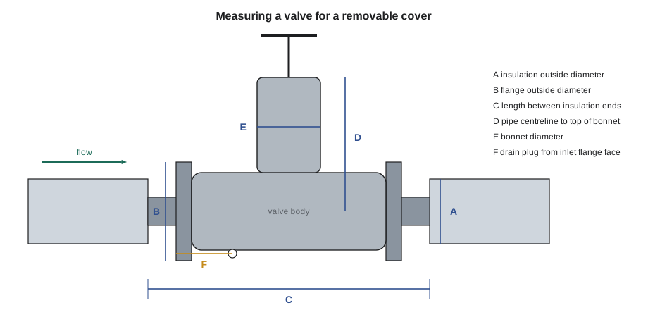
A clear sketch is as important as the numbers. Marcel draws each item roughly to scale, from the side and from the end, marks the flow direction and the stem, and writes the dimensions on the sketch as well as in the boxes. Then he takes photos from several angles with the tape in view. On the PRV body, the regulator's pilot, its sensing line and the downstream pressure gauge all had to stay accessible, so his sketch showed each one with its distance from the inlet flange face and where it pointed.
Other items
| Item | Extra measurements and notes |
|---|---|
| Flange pair | Flange OD, overall length between insulation ends, bolt projection; leave nothing bare between the cover and the insulation |
| Strainer | Body size, screen cap position and diameter, blowdown valve and its direction; screen cap removable without taking the whole cover off |
| Pressure-reducing valve | Body and actuator sizes, pilot, sensing lines, gauge and spring housing; adjustment screw and gauge must stay reachable |
| Steam trap | Trap type (some must stay bare, as INS-210 explained), body size, test valve and inlet strainer |
| Heat exchanger head | Channel or bonnet OD and length, flange OD, nozzles and their positions, nameplate, lifting lugs, bolt projection; often made in two or more pieces |
| Pump casing | Casing shape, inlet and outlet nozzles, seal and coupling areas to leave clear, drain and vent |
For the two exchanger covers, KF-HX-01 for the channel and KF-HX-02 for the bonnet, Wendell Ashby and Priya Lam measured the shell flanges, nozzles and nameplate on November 9, as INS-310 recorded. The nameplate was half covered by the old insulation, so the bonnet cover will have a framed cut-out that leaves it readable.
From measurements to a pattern
The fabricator turns the measurements into flat patterns, the shapes of fabric and mat that are cut and sewn together. The insulator does not usually draw them, but understanding how they are made explains which measurements matter most. Three ideas cover most patterns:
- Inside and outside. The inner fabric must fit around the item with a little clearance; the outer fabric is larger by twice the insulation thickness. A cover with 50 mm (2 in) of mat has an outer circumference larger than the inner by π × 2 × 50 = 314 mm.
- Closing seam and flap. A cover wraps around the pipe and closes along one side, so the outer piece has an extra flap that overlaps the closing seam and carries the fasteners.
- End closures. The ends of a cover must close against the adjacent insulation or the pipe, with a skirt and drawstring, an end panel with a hole, or an overlap onto the jacket.
Fabricators add their own seam allowances to the finished sizes. What they need from the field is the finished inside size the cover must fit around, and the size of whatever it meets at its ends.
Worked problem
Laying out a flange pair cover
An NPS 6 Class 150 flange pair on Kellerton steam has a flange OD of 279 mm. The pipe insulation on each side is 64 mm thick, with an outside diameter of 296 mm, and the gap between the insulation ends is 330 mm. The cover will have 50 mm of mat, 12 mm of clearance all round the flanges, and will overlap the insulation 50 mm at each end. Work out its finished inside diameter, inside and outside circumferences, length and the size of the outer piece with a 50 mm closing flap.
Show solution
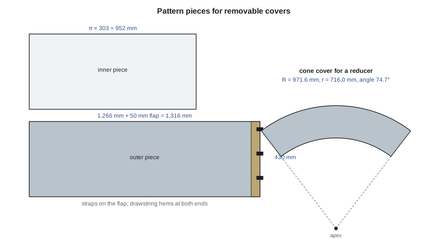
- Inside diameter = 279 + 2 × 12 = 303 mm, larger than the insulation OD of 296 mm, so the ends slide over the insulation.
- Inside circumference = π × 303 = 952 mm.
- Outside diameter = 303 + 2 × 50 = 403 mm; outside circumference = π × 403 = 1,266 mm.
- Length = 330 + 2 × 50 = 430 mm.
- Outer piece = 1,266 + 50 = 1,316 mm around, by 430 mm long, before seam allowances.
Answer: A cylinder 303 mm (12 in) inside and 403 mm (16 in) outside, 430 mm (17 in) long, with drawstrings at each end to close it onto the insulation. The outer piece is cut 1,316 × 430 mm (52 ¼ × 17 in) plus the fabricator's allowances.
Worked problem
A cone pattern for a reducer cover
A removable cover over a concentric reducer is a cone frustum. Its outside diameter is 403 mm (16 in) at the large end and 297 mm (11 ¾ in) at the small end, and it is 250 mm (10 in) long. Using radial line development, as SMW-120 and INS-220 taught, find the slant height, the two pattern radii and the angle of the pattern sector.
Show solution
- Slant height s = √(250² + ((403 − 297) ÷ 2)²) = √(62,500 + 2,809) = √65,309 = 255.6 mm.
- Pattern radius to the large end R = s × D₁ ÷ (D₁ − D₂) = 255.6 × 403 ÷ 106 = 971.6 mm.
- Pattern radius to the small end r = R − s = 971.6 − 255.6 = 716.0 mm.
- Sector angle = 360 × D₁ ÷ (2 × R) = 360 × 403 ÷ 1,943.2 = 74.7°.
Answer: The outer piece is a sector of about 75° between arcs of radius 971.6 mm (38 ½ in) and 716.0 mm (28 ¼ in), plus a flap along one straight edge. The inner piece is laid out the same way from the inside diameters.
Valve covers are more complicated: the body is usually a wrapped piece with a cut-out for the bonnet, the bonnet a separate wrapped piece or a boot, and the ends closed with drawstring skirts. Strainers need a separate cap piece so the screen can be pulled without removing the body cover. This is why fabricators prefer complete measurements and photos to a single overall size.
Checking and sending
Before sending, the measurer checks each sheet for missing dimensions, a sketch with flow and stem direction, the service and temperature, the cover number, and notes on fasteners and identification. Raj sent the PRV station sheets to Pellam with a covering list:
| Cover | Item | Notes |
|---|---|---|
| KF-BH-031 | NPS 3 inlet gate valve | Stem up; drain plug on bottom of body to stay reachable |
| KF-BH-032 | Y-strainer | Screen cap and blowdown valve downward; separate cap piece |
| KF-BH-033 | PRV body | Pilot, sensing line and gauge to stay reachable; spring housing left bare |
| KF-BH-034 | PRV outlet flange pair | Cylinder with drawstring ends |
| KF-BH-035 | NPS 6 outlet gate valve | Stem up; nameplate on bonnet to stay readable |
Ferris called Raj the same afternoon with one question: was the PRV's spring housing to be covered? The sheet said bare, but the sketch showed the cover running up to it. Marcel confirmed it was to stay bare, because the plant adjusts it, and corrected the sketch. One phone call at the sketch stage is much cheaper than a cover remade after delivery.
Digital measuring
Some fabricators now accept measurements from phone apps that record dimensions against a photo, or from 3D scans of the item. These tools speed up large surveys, but they do not replace a careful look at the item: an app does not know that a drain plug must stay reachable or that a spring housing is adjusted by the operators. Marcel's sheets for the PRV station were still on paper, with photos to back them up, because the questions that matter are the ones a person has to ask.
Common mistakes
MistakeSending only an overall size for a valve cover.
InsteadMeasure every lettered dimension on the fabricator's sheet, sketch the item and take photos with a tape in view.
MistakeForgetting the adjacent insulation size.
InsteadMeasure the outside diameter and cutback of the insulation on each side; the cover must meet it.
MistakeLeaving out drains, gauges and nameplates.
InsteadLocate everything that must stay reachable or visible, with distances from a reference face.
MistakeMeasuring hot or moving equipment unsafely.
InsteadMeasure cold where possible; on live lines use gloves, a long tape and photos, and do not reach over hot or rotating parts.
MistakeLeaving items unnumbered.
InsteadTag each item and use the same number on the sheet, the photos and the cover.
Summary and key terms
- Insulators usually measure covers and send the information to a blanket fabricator on the fabricator's measurement sheets.
- Measure the item, the adjacent insulation, the service and everything that must stay reachable or visible, and sketch the item with flow and stem direction.
- Number every item and use the number on the tag, the sheet, the photos and the cover.
- Patterns use inside and outside sizes, closing flaps and end closures; cone covers are laid out by radial line development.
- Check every sheet before sending and resolve questions with the fabricator before cutting.
- Blanket fabricator
- A specialist shop that cuts and sews removable insulation covers.
- Measurement sheet
- A fabricator's form with a drawing and lettered dimensions for a type of item.
- Pattern
- A flat shape of fabric or mat cut and sewn to make a cover.
- Closing flap
- An extra piece of outer fabric that overlaps the closing seam of a cover and carries its fasteners.
- Drawstring
- A cord in the end hem of a cover, pulled tight to close it onto the adjacent insulation or pipe.
- Cutback
- The distance by which insulation stops short of a flange or fitting.
- Slant height
- The length along the sloping side of a cone frustum, used in its pattern.
Practice problems
Work each problem on paper first, then reveal the answer to check.
Why must the adjacent insulation size be measured for a cover?
Show answer
The cover's ends must fit over or against it, with no bare gap.
A flange cover has an inside diameter of 350 mm (14 in) and 50 mm (2 in) of mat. What is its outside circumference?
Show answer
π × 450 = 1,414 mm.
Why is a strainer cover made with a separate cap piece?
Show answer
So the screen can be removed without taking the whole cover off.
What should a valve sketch always show besides dimensions?
Show answer
The direction of flow, the direction of the stem, and anything that must stay reachable or visible.
What is the length of a flange cover for a 300 mm (12 in) gap with 50 mm (2 in) overlap at each end?
Show answer
400 mm (16 in).
Lesson quiz · 5 questions
Score 60% or more to complete this lesson.
Create a free account to save your progress, take quizzes and earn a certificate.