
INS-340 · Lesson 3 of 12 · 24 min
Acoustic lagging on piping
▶ Video coming soon A video version of this lesson is on the way.
Coldstream started on Compressor No. 5 on Tuesday, August 4, 2026, the day after the Civic Holiday. Bernie Valois walked the engine room with Wendell and Priya in the morning to write the hazard sheet: ammonia, hot pipe at about 80 °C (175 °F) on the discharge line, noise around 95 dBA on the walkway, a lift for the high runs, and the other four compressors running throughout. By noon the crew had the first lengths of mineral wool pipe section on the NPS 6 discharge line between the oil separator and the engine room wall.
Acoustic lagging is the name for insulation systems built to reduce the noise radiated by pipes, valves and flanges. On refineries, gas plants and compressor stations it covers kilometres or miles of pipe; in food plants and buildings it is used where a pipe runs past offices or near property lines. This lesson covers why pipes radiate noise, the international standard that sets classes of lagging, how a lagging system is built and why each layer is there, the details at supports, ends and penetrations, and the mistakes that cost the most performance.
Why pipes radiate noise
A pipe is a long, thin-walled shell, and noise in the fluid inside makes its wall vibrate and radiate. The main sources are:
- Control valves and pressure-reducing valves. High pressure drops make turbulence and, in gas or steam, very high-frequency noise that travels downstream for long distances. Valve noise is the most common reason for lagging in process plants.
- Compressors and pumps. Positive displacement machines, such as screw and reciprocating compressors, send pressure pulsations into the piping at the lobe-passing or stroke frequency and its harmonics, giving strong tones like the 237 Hz tone of Compressor No. 5.
- High-velocity flow. Gas flowing fast through elbows, tees, reducers and orifices makes broadband noise.
- Mechanical vibration. A machine shakes the pipe directly, and the pipe passes the vibration on to its supports and to the building.
Because the noise travels along the pipe inside the fluid, a lagging job usually covers the pipe from the source to a point where the noise has died away or the pipe leaves the area of concern, including every valve, flange and fitting on the way. A short lagged section with bare pipe on either side achieves little.
ISO 15665: classes of lagging
The international standard for acoustic insulation of pipes, valves and flanges is ISO 15665. Its 2023 edition replaced the 2003 edition and brought in a fourth class that had been used in industry for large pipes. The standard does not prescribe one construction; it sets minimum insertion loss values that a system must meet, proved by testing.
- Classes A, B, C and D. Class A is the lowest performance and Class C or D the highest. Each class has minimum insertion loss values in each of seven octave bands from 125 to 8,000 Hz, and a system that misses any band does not earn the class. Class D applies to the larger pipe sizes.
- Pipe diameter ranges. The requirements depend on the pipe's outside diameter: under 300 mm, 300 mm to under 650 mm, and 650 mm to under 1,000 mm, because larger pipes behave differently.
- Materials. The porous layer may be mineral wool, glass wool, and, since 2023, flexible elastomeric foam and aerogel blankets, provided the tested system meets the class. Example constructions are given in an informative annex, but they are guidance only; the class is proved by tests on the actual system.
- Removable jackets. The standard covers removable acoustic jackets for valves and flanges and sets how far they must overlap the fixed lagging on each side: 100 mm (4 in) for Class A, 200 mm (8 in) for Class B and 300 mm (12 in) for Classes C and D.
- Corrosion. The 2023 edition draws attention to corrosion under insulation and favours porous materials and spacer details that limit moisture held against the pipe.
In North American buildings and food plants, acoustic lagging is often specified by the acoustical consultant directly, in insertion loss by octave band, as Sunniva did, rather than by ISO class. The principle is the same: the installed system must match the system that was tested.
How a lagging system is built
A typical lagging system has three layers, from the pipe outward:
- Porous layer (absorber and decoupler). Mineral wool or glass wool pipe section, or flexible blanket, usually 25 to 100 mm (1 to 4 in) thick. It absorbs sound in the space between the pipe and the barrier and, just as important, acts as a soft spring that isolates the barrier from the vibrating pipe wall. It must not be crushed; a compressed porous layer passes vibration straight through.
- Barrier (mass) layer. A limp, heavy layer, most often mass-loaded vinyl of about 5 to 10 kg/m² (1 to 2 lb/ft²), or a composite of mass layer bonded to a foam or fibre decoupler. Higher classes use more mass, or two barrier layers separated by a second porous layer.
- Jacket (cladding). Aluminum or stainless steel sheet, which protects the system, adds some mass and, if well sealed, forms part of the barrier. Some lightweight systems use the jacket alone as the barrier, with a damping compound on its inside face to stop it ringing.
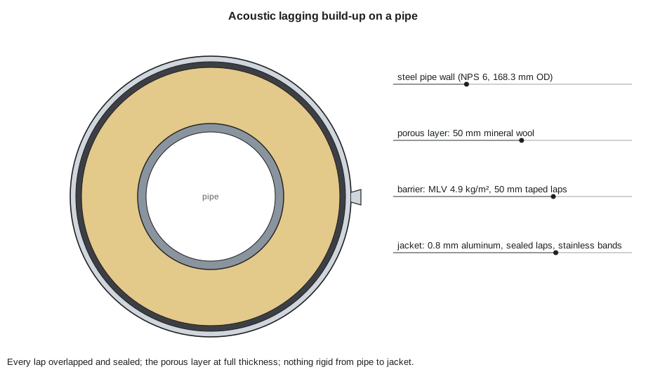
Sunniva's specification for the discharge line called for 50 mm (2 in) of mineral wool pipe section, one layer of mass-loaded vinyl of 4.9 kg/m² (1 lb/ft²) with 50 mm (2 in) lapped and taped seams, and 0.8 mm (0.032 in) aluminum jacket with sealed laps and stainless steel bands. Coldstream's submittal included the maker's test report for that exact build-up on a pipe of similar size, which met her octave band values.
Worked problem
How much barrier for the discharge line?
The NPS 6 discharge line (168.3 mm (6.625 in) outside diameter) runs 22 m (72 ft) from the oil separator to the wall. The mineral wool is 50 mm (2 in) thick, and the barrier seams overlap 50 mm (2 in). Rolls of barrier hold 12 m² (120 ft²). Allowing 10 in 100 for waste and for wrapping fittings, how many rolls are needed, and how much weight does the barrier add per metre (foot)?
Show solution
- Diameter over the mineral wool = 168.3 + 2 × 50 = 268.3 mm.
- Circumference = π × 268.3 = 842.9 mm; with the 50 mm overlap, cut width = 892.9 mm, about 893 mm.
- Area = 0.893 × 22 = 19.6 m²; with 10 in 100 extra: 19.6 × 1.10 = 21.6 m².
- Rolls = 21.6 ÷ 12 = 1.8, so 2 rolls.
- Weight per metre = 0.893 × 4.9 = 4.4 kg/m; total about 4.9 × 19.6 = 96 kg.
Answer: Two rolls. The barrier adds about 4.4 kg/m (2.9 lb/ft) to the pipe, plus the jacket and mineral wool, so the refrigeration contractor checked the existing supports before the lagging went on.
Worked problem
Cutting the jacket over the barrier
The barrier is about 3 mm (⅛ in) thick. With a 50 mm (2 in) overlap on the longitudinal seam, what width should the aluminum jacket be cut for the discharge line?
Show solution
- Diameter over the barrier = 268.3 + 2 × 3 = 274.3 mm.
- Circumference = π × 274.3 = 861.7 mm.
- Cut width = 861.7 + 50 = 911.7 mm, about 912 mm.
Answer: About 912 mm (36 ¼ in). Priya measured the first wrapped length with a strap before cutting, as Tomasz teaches, and it came to within 3 mm (⅛ in) of the calculation.
Installing the layers
Lagging is installed in much the same order as thermal pipe insulation, with stricter rules on joints and contact:
- Porous layer. Pipe sections are fitted tight, with butt joints staggered and longitudinal joints on the sides, and held with wire or tape. Blanket is wrapped and tied without compressing it below its rated thickness. Gaps are packed with loose mineral wool.
- Barrier. Wrapped with the longitudinal seam overlapping at least 50 mm (2 in) and turned to shed water, and the circumferential joints overlapped the same amount. Every seam is sealed with the tape the barrier maker specifies, or with a contact adhesive. The barrier must not be stretched tight enough to compress the porous layer.
- Jacket. Applied over the barrier with overlapped and sealed laps, fixed with bands rather than screws where possible, because screws can pin the jacket through the barrier to the porous layer and, if too long, touch the pipe. Where screws are needed, they must be short enough to stay clear of the pipe.
- Fittings. Elbows, tees and reducers are lagged with the same layers, using gored or segmented sections and cut barrier pieces, with no gaps at the joints between fitting and straight pipe.
On the discharge line, Wendell had Priya tape a test seam on the first morning and pull it after an hour to check that the tape held on the vinyl at the engine room temperature. It did; on another job, a barrier that had been stored in a cold trailer had a slick surface film, and the crew wiped it with the maker's cleaner first.
Supports, ends and penetrations: no sound bridges
Most lagging failures happen at the places where the system meets something solid. Each of these is a possible sound bridge or leak:
- Pipe supports. A clamp or shoe welded or bolted to the pipe carries vibration straight to the outside. The lagging must be carried continuously over the support, with the barrier and jacket boxed around the clamp and the rod or saddle sealed where it passes through, never with the jacket resting on the clamp. Better still, the support itself is isolated with a resilient pad or spring hanger, which is the piping contractor's work.
- Ends of the lagging. Where the lagging stops, at a flange of equipment or a wall, the end is closed with an end cap that seals the barrier to the jacket and a soft seal against the pipe, so the jacket does not touch the pipe.
- Wall and floor penetrations. The lagging is carried into the sleeve where possible, and the annular space is sealed with a resilient sealant so the pipe does not drive the wall. At a fire-rated wall, the firestop system must be listed for the lagged pipe, as INS-330 explained.
- Valve stems, instrument connections and drains. Openings in the barrier for stems and small connections are cut close and sealed with a flexible boot or tape; they are the most common leaks.
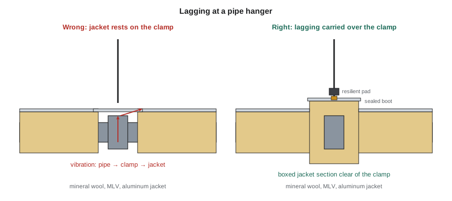
The engine room discharge line had four supports between the separator and the wall. Before Coldstream started, the plant's refrigeration contractor replaced the two rigid hangers nearest the compressor with spring hangers, on Sunniva's recommendation, and fitted neoprene pads under the two saddles near the wall. Priya boxed each clamp with oversized jacket sections and sealed the rod openings with the maker's boots.
Acoustic lagging and thermal service
Acoustic lagging is also insulation, and its thermal effects must be thought through:
- Hot lines. The porous layer limits heat loss and keeps the jacket cool to touch, but the barrier must stay below its temperature limit, often around 80 to 100 °C (175 to 210 °F) for vinyl barriers; check the maker's data. On hotter lines, thicker or two-part porous layers put the barrier further out, as lesson 8 shows.
- Cold lines. The system must include a continuous vapour retarder with sealed joints, usually as the first layer outside the porous material or as a jacket facing, or the porous layer will fill with condensation and frost, as INS-320 explained.
- Lines that are normally bare. Some lines, such as refrigerant discharge lines, are left bare on purpose to reject heat. Lagging them changes how much heat they give off. On Compressor No. 5, the refrigeration contractor confirmed that the small reduction in heat lost from the discharge line made no difference to the condenser load.
- Corrosion under insulation. Lagging traps moisture just like thermal insulation, and carbon steel lines in the range where corrosion is fastest need the same care with jackets, sealing and coatings that INS-220 described.
What happens if the system is wrong
Acoustic performance falls off much more sharply than thermal performance when the workmanship is poor. Consultants who test installed lagging often find the same faults: compressed porous layers under tight bands, unsealed barrier seams, bare valves and flanges left for later, and jackets touching supports. Any one of these can cut the insertion loss in the important bands by 5 to 10 dB, which can be the difference between a solved problem and a repeat complaint.
When the discharge line was finished on Friday, August 7, Wendell walked it end to end with Priya, tapping the jacket with a knuckle every metre (few feet). A dull thud meant a well-decoupled jacket; a ringing tone at one support meant the jacket was touching the clamp, and Priya reset the box section before they left.
Common mistakes
MistakeLagging only the straight pipe and leaving valves and flanges bare.
InsteadLag the whole radiating length, including every valve, flange and fitting, or cover them with removable acoustic covers.
MistakePulling bands or barrier so tight that the porous layer is crushed.
InsteadKeep the porous layer at full thickness so it decouples the barrier from the pipe.
MistakeLetting the jacket rest on a pipe clamp or support.
InsteadBox the lagging over the support and seal the rod or saddle; isolate the support where possible.
MistakeLeaving barrier seams untaped because the jacket covers them.
InsteadOverlap and seal every barrier seam; the jacket alone does not make the barrier airtight.
MistakeInstalling a different build-up from the tested system.
InsteadInstall the exact system in the test report, or get the consultant's approval for any change.
Summary and key terms
- Pipes radiate noise from valves, compressors, pumps, high-velocity flow and vibration; lagging must cover the whole radiating length.
- ISO 15665:2023 sets Classes A, B, C and D by minimum insertion loss in seven octave bands, for three pipe diameter ranges, proved by tests on the actual system.
- Lagging has a porous layer that absorbs and decouples, a barrier layer that adds mass, and a jacket that protects and seals.
- Seams must be overlapped and sealed, the porous layer kept at full thickness, and screws kept clear of the pipe.
- Supports, ends, penetrations and stems are the common sound bridges and leaks; the jacket must never touch the pipe or its clamps.
- Acoustic lagging also affects heat flow: keep barriers below their temperature limit on hot lines and add vapour retarders on cold lines.
- Acoustic lagging
- An insulation system built to reduce noise radiated from pipes, valves and flanges.
- ISO 15665
- The international standard for acoustic insulation of pipes, valves and flanges, with Classes A to D.
- Porous layer
- The absorbing, decoupling layer of a lagging system, such as mineral wool.
- Barrier layer
- The heavy, limp layer of a lagging system, such as mass-loaded vinyl.
- Sound bridge
- A rigid contact that carries vibration past a decoupling layer.
- Spring hanger
- A pipe hanger with a spring that isolates the pipe's vibration from the structure.
- End cap
- A closure that seals the end of a lagging system and keeps the jacket off the pipe.
- Lobe-passing frequency
- The frequency at which the lobes of a screw compressor rotor pass the discharge port.
Practice problems
Work each problem on paper first, then reveal the answer to check.
Why must lagging cover valves and flanges as well as straight pipe?
Show answer
Bare valves and flanges radiate strongly and act as gaps in the treatment, so the insertion loss of the whole line falls.
What are the two jobs of the porous layer in lagging?
Show answer
To absorb sound between the pipe and the barrier, and to decouple the barrier from the vibrating pipe.
A removable jacket is used with Class B lagging. How far should it overlap the fixed lagging?
Show answer
200 mm (8 in) on each side.
What cut width of barrier is needed for an NPS 4 pipe (114.3 mm (4.5 in)) with 50 mm (2 in) of mineral wool and a 50 mm (2 in) overlap?
Show answer
π × 214.3 + 50 = 673 + 50 = 723 mm.
Why are bands preferred to screws on an acoustic jacket?
Show answer
Screws can pin the jacket through the barrier and, if too long, touch the pipe, making a sound bridge.
Lesson quiz · 5 questions
Score 60% or more to complete this lesson.
Create a free account to save your progress, take quizzes and earn a certificate.