
FAT-130 · Lesson 9 of 12 · 19 min
Voltage drop on notification appliance circuits
Ravi Menon spreads the Cartwright Distribution Centre drawings across the table in Bramwell's design office and points to the dock wall. 'The longest circuit on the dock wall: fourteen horn-strobes in a line, 170 m from the remote supply to the last one,' he says. 'This is the circuit that will fail first in a long blackout, so it's the one we calculate most carefully.' He shows Sasha two ways to do it: the quick, conservative method that assumes all the load is at the far end, and the point-to-point method that follows the current along the wire. This lesson covers both, the worst-case conditions they assume, and what to do when a circuit doesn't pass.
Why voltage drop is the critical calculation
A notification appliance must receive at least its minimum listed voltage to operate as listed: to flash at its rated candela, to sound at its rated level, and to stay synchronized with its neighbours. For 24-volt appliances, that minimum is commonly 16 volts. The panel or power supply provides more than 24 volts on primary power, but at the end of the battery's standby period, with every appliance in alarm, the source voltage is much lower. The wiring between the source and the appliances then takes its share, and the last appliance on the circuit gets whatever is left. The calculation proves that what is left is enough.
CAN/ULC-S524 requires the notification appliance circuits to be designed so that every appliance receives its rated operating voltage under the worst-case conditions, and the design documents to show the calculation. The panel maker's installation manual gives the minimum source voltage to use, and some makers publish their own calculation method.
Worst-case conditions
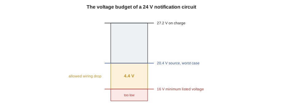
Voltage drop calculations use three worst-case assumptions together. The source voltage is the lowest the panel or supply will provide at the end of its battery's required duration, which is commonly taken as 20.4 volts, the end-of-discharge voltage of a 24-volt lead-acid battery, or a figure the maker specifies. The appliance current is the maximum listed current for the installed setting over the operating range, not the current at 24 volts. And the wire resistance is taken at a warm temperature, such as 75 °C (167 °F), or from the maker's published table.
With 20.4 volts at the source and 16 volts needed at the last appliance, a circuit can lose at most 4.4 volts in its wiring. That allowance, about 21.5 percent of the source voltage, is the budget the design must stay within. Many designers keep a margin, aiming for 17 or 18 volts at the last appliance rather than 16, so that minor changes during construction don't push the circuit over.
Method 1: the lumped load
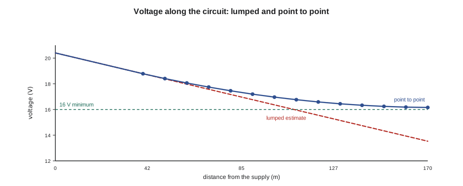
The simplest calculation assumes that all the appliances' current flows through the whole length of the circuit, as if every appliance were at the far end. The drop is the total current times the loop resistance of the full circuit. This overestimates the drop, because the appliances near the panel draw their current through only a short length of wire, but it is quick and always errs on the safe side. If a circuit passes the lumped method, it passes. If it fails, the more accurate point-to-point method may show that it actually passes.
Here I with subscript total is the sum of the appliances' maximum currents, L is the one-way length to the last appliance, and r is the resistance per unit length of one conductor. The factor of 2 counts both conductors.
# Lumped-load voltage drop for the Cartwright dock wall
I_total = 14 * 0.143          # 14 horn-strobes at 30 cd, maximum listed current, A
length = 170                  # one-way, m
r = {"16": 16.0, "14": 10.1, "12": 6.34}   # ohm per km per conductor
V_source, V_min = 20.4, 16.0
for g in ("16", "14", "12"):
    drop = I_total * 2 * length * r[g] / 1000
    v_end = V_source - drop
print(f"{g} AWG: drop {drop:4.2f} V, last appliance {v_end:5.2f} V {'pass' if v_end >= V_min else 'fail'}")16 AWG: drop 10.89 V, last appliance 9.51 V fail 14 AWG: drop 6.87 V, last appliance 13.53 V fail 12 AWG: drop 4.32 V, last appliance 16.08 V pass
By the lumped method, 16 AWG and 14 AWG both fail, and 12 AWG only just passes.
Method 2: point to point
The point-to-point method follows the current along the circuit. The circuit is divided into segments between appliances. The first segment, from the source to the first appliance, carries the current of every appliance. The second carries the current of every appliance except the first, and so on, until the last segment carries only the last appliance's current. The drop in each segment is its current times its loop resistance, and the voltage at each appliance is the voltage at the previous one minus the drop in the segment between them.
Here V with subscript n is the voltage at appliance n, I with subscript n is the current in the segment leading to it, the sum of the currents of appliance n and every appliance beyond it, and ℓ with subscript n is the segment's one-way length. Because strobes draw more current at lower voltage, a precise calculation would recalculate each appliance's current at its own voltage; using the maximum listed current for every appliance covers this without iteration.
# Point-to-point voltage drop for the Cartwright dock wall
n = 14
I_app = 0.143                 # maximum listed current for each appliance, A
first, spacing = 40, 10   # one-way distance to the first appliance and between appliances, m
r = 10.1 / 1000                # 14 AWG, ohm per m per conductor
v = 20.4
print(" appliance   segment current   voltage")
for k in range(1, n + 1):
    seg = first if k == 1 else spacing
    current = (n - k + 1) * I_app
    v -= current * 2 * seg * r
    if k in (1, 2, 7, 13, 14):
        print(f"   {k:3d}          {current:5.3f} A        {v:5.2f} V")
print(f"last appliance: {v:.2f} V, {'pass' if v >= 16 else 'fail'}") appliance segment current voltage
1 2.002 A 18.78 V
2 1.859 A 18.41 V
7 1.144 A 16.96 V
13 0.286 A 16.18 V
14 0.143 A 16.15 V
last appliance: 16.15 V, passThe point-to-point method gives a higher voltage at the last appliance than the lumped method, 16.15 volts instead of 13.5, because the current falls as it passes each appliance. On 14 AWG the circuit passes, but with almost no margin: a single added appliance or a slightly longer run would push it under. Ravi specifies 12 AWG for this circuit, which gives about 17.7 volts at the last appliance point to point, and notes on the drawing why the gauge is larger than the others.
Where the appliances are matters
The point-to-point method shows how much the layout matters. The same fourteen appliances on the same length of wire produce very different voltages at the end depending on where they are. If they are bunched near the start of the circuit and the last one is far away, the drop is small. If they are bunched at the far end, the drop approaches the lumped-load result. A long 'home run' from the panel to the first appliance, carrying the full circuit current, is the most costly part of a circuit; that is why remote power supplies are placed near the appliances they serve.
When a circuit fails
When the calculation shows the last appliance below its minimum, there are several fixes, roughly in order of preference. Use the point-to-point method instead of the lumped one; it may pass. Reduce the load: lower candela settings where the room sizes allow it, or use horns without strobes where strobes aren't required. Split the circuit into two, each with half the appliances. Use a larger wire gauge. Move the source closer by adding a remote power supply. The designer picks the fix; the technician's job is to make sure the installed circuit matches what was calculated, and to tell the designer when it doesn't.
# Effect of splitting a circuit in two (lumped estimate, 14 AWG, illustrative)
I_each, n, r_loop_per_unit = 0.264, 12, 0.0202   # A, appliances, ohm per unit length out and back
length = 120
whole = n * I_each * length * r_loop_per_unit
half = (n // 2) * I_each * length * r_loop_per_unit
print(f"one circuit of {n}: drop {whole:.2f} V")
print(f"two circuits of {n // 2}: drop {half:.2f} V each")one circuit of 12: drop 7.68 V two circuits of 6: drop 3.84 V each
Checking in the field
After installation, the calculation is verified by measurement. With the system on battery, and ideally with the battery partly discharged or the source voltage set to its worst-case value with a bench supply where the maker allows it, the circuit is put in alarm and the voltage at the last appliance is measured. The reading is compared with the calculation, adjusted for the actual source voltage at the time. A reading lower than expected points to a longer run than drawn, a smaller gauge, extra appliances, or a bad connection. A reading near the minimum, even if it passes, deserves a note on the test record.
Measurements at the last appliance also reveal problems the calculation can't: corroded splices, loose terminals and damaged conductors, each of which adds resistance that isn't on the drawings. Sasha's Willowbank strobe in lesson 2 was found exactly this way.
Worked problem
Riverlight Tower's corridor circuit
A corridor circuit on Riverlight Tower's 9th floor has eight horn-strobes at 75 cd, each with a maximum listed current of 0.264 A, on 14 AWG. The remote supply is in the 6th-floor electrical room, and the riser and corridor run is 95 m to the last appliance, with the first appliance at 60 m. Does it pass by the lumped method?
Show solution
- Total current: 8 × 0.264 = 2.11 A.
- Loop resistance: 2 × 95 m × 10.1 Ω/km = 1.92 Ω.
- Lumped drop: 2.11 × 1.9 = about 4.0 V, giving 20.4 − 4.0 = 16.4 V at the last appliance.
- It passes, but with only 0.4 V to spare, so the point-to-point method is worth running before anything else is added.
Answer: Point to point, the last appliance gets about 17.1 V, because the first 60 metres carry the whole current but the appliances are spread along the corridor beyond it. Ravi notes on the drawing that this circuit has no spare capacity for additions.
Voltage drop and synchronization
Voltage drop affects more than whether an appliance works. Strobes in the same field of view must flash in synchrony, because flashing at different moments can trigger seizures in people with photosensitive epilepsy and is more confusing for everyone. Synchronization is carried on the notification circuit itself, as brief interruptions or coded pulses in the power, or through a separate sync module. A strobe at the end of a long circuit with a large voltage drop may still flash, but it may charge too slowly to flash on the synchronizing pulse, and drift out of step with the others. A voltage drop calculation that leaves a comfortable margin also protects synchronization.
Low voltage also affects horns and speakers. An electronic horn may still sound below its minimum voltage, but more quietly than its rated output, so a space whose audibility was measured on primary power may fall short when the system is on battery. This is another reason the worst-case calculation matters: the measurements at verification are usually taken on primary power, and the calculation is what shows the system will still meet its requirements on battery.
Finally, a design that leaves a margin is a design that tolerates the changes every building goes through: a corridor rerouted, a wall moved, an appliance added in a renovation. Ravi's practice of aiming for 18 volts at the last appliance, instead of 16, gives each circuit room for some of those changes without immediate redesign.
Common mistakes
MistakeUsing the battery's full-charge voltage as the source.
InsteadUse the end-of-discharge voltage, commonly 20.4 V, or the maker's figure.
MistakeUsing appliance current at 24 V.
InsteadUse the maximum listed current for the installed setting.
MistakeCounting only one conductor's length.
InsteadThe loop is out and back: twice the one-way length.
MistakeCalling a lumped-load failure final.
InsteadRun point to point; it may pass.
MistakeAdding appliances to a circuit without rechecking.
InsteadEvery addition changes the drop for every appliance beyond it.
Summary and key terms
- Every notification appliance must receive its minimum listed voltage, commonly 16 V, in the worst case.
- The worst case combines the lowest source voltage, the maximum appliance current and warm wire.
- From 20.4 V at the source to 16 V leaves a 4.4 V wiring budget.
- The lumped method is quick and conservative; point to point is more accurate.
- Fixes: lower settings, split circuits, larger wire or a closer power supply.
- Field measurements in alarm verify the calculation and expose bad connections.
- Voltage drop calculation
- A calculation of the voltage at each notification appliance under worst-case conditions.
- End-of-discharge voltage
- The lowest battery voltage assumed at the end of the required duration, commonly 20.4 V.
- Lumped load
- A conservative method that places all the current at the end of the circuit.
- Point-to-point method
- A method that calculates the voltage at each appliance in turn.
- Home run
- The length of circuit from the source to the first appliance.
- Voltage budget
- The drop a circuit may have between the source and the last appliance.
Practice problems
Work each problem on paper first, then reveal the answer to check.
A circuit carries 1.5 A through 2 × 120 m of 14 AWG. What is the lumped drop?
Show answer
About 3.6 V (1.5 × 240 m × 10.1 Ω/km).
With 20.4 V at the source, what is the lowest drop that leaves 16 V?
Show answer
4.4 V.
Why does the point-to-point method give a higher last-appliance voltage?
Show answer
Appliances near the start draw their current through only a short length of wire.
Name two fixes for a circuit that fails.
Show answer
Split it, use a larger gauge, lower the settings or add a remote supply.
Lesson quiz · 5 questions
Score 60% or more to complete this lesson.
Create a free account to save your progress, take quizzes and earn a certificate.