
FAT-130 · Lesson 4 of 12 · 19 min
Meters and measurement for fire alarm work
Sasha's first tool purchase as a second-year trainee is a digital multimeter, and Gerry makes her bring it to class still in its box. 'Before you measure anything in a live panel,' he says, 'you need to know what your meter can do, what it can't, and how it can hurt you if you set it wrong.' A meter is the fire alarm technician's most used diagnostic tool. It confirms that power is present and absent, measures battery voltage and charging current, finds opens and shorts, checks end-of-line resistors, and measures the voltage at the last appliance in alarm. This lesson covers the meters the trade uses, how to use them safely, and how to interpret what they show.
The digital multimeter
A digital multimeter measures voltage, both DC and AC, resistance and continuity, and current, usually with a separate jack and a fuse for current measurement. Most also measure diode junctions and capacitance, and better meters record minimum and maximum readings, which is useful for catching a voltage dip during an alarm. True-RMS meters measure alternating voltages and currents accurately even when the waveform is not a clean sine wave, which matters when measuring the output of some power supplies and the full-wave rectified outputs of some panels.
A meter used on building power must have a safety category rating, marked CAT II, III or IV with a voltage, that matches the circuits it will touch. A fire alarm panel's primary supply comes from a branch circuit in the building, which is a CAT III location. The meter, its leads and its probes should all carry a CAT III or higher rating at 600 volts or more, and the meter should be certified to the CSA or IEC safety standard for measuring instruments. A cheap meter without a rating can explode in the technician's hand if it is used on a circuit with a high-energy fault.
Measuring voltage
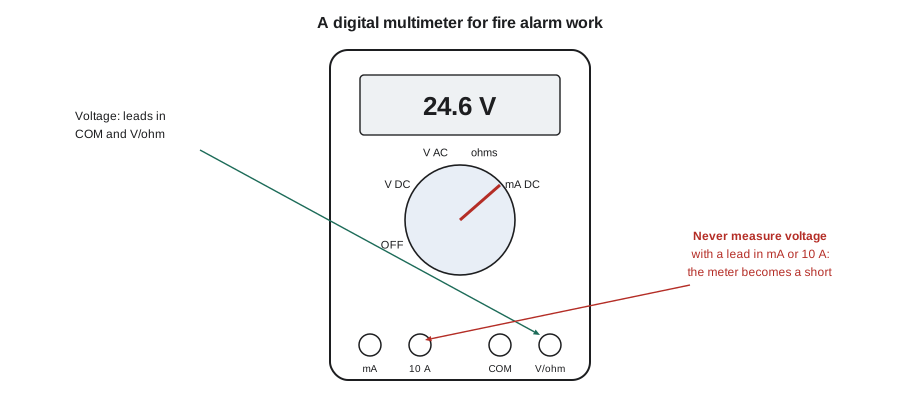
Voltage is measured across a component, with the meter in parallel: one lead on each side. The meter draws almost no current, so it doesn't disturb the circuit. In fire alarm work, the common voltage measurements are the panel's notification outputs, battery voltage, the voltage at an appliance during an alarm, the auxiliary power output, and the primary AC supply at the panel's terminals. DC voltage readings have a polarity: if the red lead is on the negative conductor, the meter shows a minus sign. On a notification circuit, the polarity reverses between standby and alarm, because the panel supervises the circuit with reverse polarity when idle, so a reading taken in standby shows a small reversed voltage, and one taken in alarm shows the full output.
A voltage reading is only meaningful under the right conditions. The voltage at a strobe with the circuit idle tells you almost nothing; the drop that matters only appears when the appliances draw their full current, so voltage at the last appliance is measured with the system in alarm. Battery voltage on charge tells you the charger is working, not that the battery is healthy; a battery's condition is judged by its voltage under load, or by a load test.
Measuring resistance and continuity
Resistance is measured with the circuit de-energized, because the meter supplies its own small test current and any other voltage will spoil the reading or damage the meter. In fire alarm work, resistance is used to check end-of-line resistors, measure the loop resistance of a pair of conductors, and look for shorts and ground faults on wiring that is disconnected from the panel. Continuity is a resistance test with a beep, useful for confirming which conductor is which at the far end of a run.
To measure the loop resistance of a circuit, a technician disconnects it from the panel, shorts the two conductors together at the far end, and measures between them at the panel end. The reading is the resistance of both conductors in series, which can be compared with what the wire gauge and length should give. A reading much higher than expected points to a bad splice or a longer run than the drawing shows. With the short removed and the end-of-line device in place, the meter should read the end-of-line value plus the small wire resistance.
# Is the measured loop resistance reasonable for the run? (illustrative)
ohm_per_km = {"18": 25.5, "16": 16.0, "14": 10.1, "12": 6.34}   # copper, one conductor
gauge, length = "14", 180       # one-way length of the circuit
expected = 2 * length * ohm_per_km[gauge] / 1000
measured = 6.8
print(f"{gauge} AWG, one-way {length} m: expected loop {expected:.2f} ohm, measured {measured:.2f} ohm")
ratio = measured / expected
print("looks normal" if ratio < 1.15 else f"{ratio:.1f} times expected: look for a bad splice or a longer run")14 AWG, one-way 180 m: expected loop 3.64 ohm, measured 6.80 ohm 1.9 times expected: look for a bad splice or a longer run
Measuring current
Current is measured in series: the circuit is opened and the meter inserted so that the current flows through it. That is awkward on live fire alarm circuits, and dangerous if the meter is set wrong, because a meter on its current setting is nearly a short circuit. Most current measurement in fire alarm work therefore uses one of two other methods. A DC clamp meter measures current by sensing the magnetic field around a conductor, without breaking the circuit; it is the easiest way to measure a notification circuit's alarm current or a battery's charging and discharge current. The other method is to measure the voltage across a known resistance, such as a shunt, and use Ohm's law.
Standby current, the small current a panel and its devices draw from the battery when the power is off, is one of the most useful measurements a technician can make, because it checks the battery calculation against reality. With the primary power switched off, the technician clamps around the battery lead and reads the panel's standby current. If it is much higher than the calculation assumed, something has been added to the system since it was designed, or something is faulty.
Insulation resistance testing
A multimeter's resistance range measures with a few volts, which is enough to find a dead short but not a weak spot in a cable's insulation. An insulation resistance tester applies a higher test voltage, often 250 or 500 volts DC, and measures leakage through the insulation, reading in megohms. It is used on new installations, and when hunting ground faults that the panel reports but a multimeter cannot find. It must never be used on a circuit with devices connected: the test voltage will destroy detectors, modules and appliances. The conductors are disconnected from the panel and from every device, or the test is done before devices are installed.
Many fire alarm installation standards and specifications require the field wiring to be tested for opens, shorts and grounds before devices are connected, and the results recorded. A reading in the hundreds of megohms between each conductor and ground is typical of good new wiring; a reading in the low megohms or less shows damaged insulation or moisture.
Measuring safely
Gerry's rules for meters are short. Check the meter on a known source before and after measuring for the absence of voltage, so that a dead meter can't fool you. Set the function before touching the probes to anything. Never measure voltage with a lead in the current jack. Use probes with finger guards and short exposed tips. Work one hand at a time when probing line voltage. And when a panel's cabinet is open, treat its primary terminals as live until you have measured them dead.
Fire alarm work brings one more safety consideration. A meter or a test lead that accidentally shorts an initiating circuit, or a technician who disconnects a circuit to measure it, can cause an alarm or a trouble that reaches the monitoring station and the building's occupants. Before measuring on a live system, the technician arranges with the monitoring station to place the account on test, and tells the building's staff that testing is under way.
Worked problem
Checking a battery at Eastview General
During Eastview General Hospital's annual inspection, Sasha checks a remote power supply. With primary power on, the battery terminals read 27.3 V. She switches off the supply's primary power and clamps the battery lead: 0.42 A. After a few minutes, the battery reads 25.4 V. Then she triggers the power supply's notification circuits with the panel in test: the current rises to 4.1 A and the battery drops to 24.6 V. What do these readings tell her?
Show solution
- 27.3 V on charge shows the charger is working at a typical float voltage for a 24 V lead-acid battery.
- 25.4 V at a 0.42 A standby load is healthy for a charged battery.
- Under a 4.1 A alarm load, the battery holds 24.6 V, a small sag that suggests good capacity.
- The 0.42 A standby current can be compared with the battery calculation on file; a large difference would mean the calculation is out of date.
Answer: The readings are good, but the batteries' date label shows they are four years old, so Sasha notes them for replacement planning. The calculation on file assumed 0.31 A standby; she finds that two duct detector modules were added in a renovation, and flags the calculation for revision.
Taking readings that mean something
A reading is only as good as the conditions it was taken under, and a good technician records the conditions with the number. A battery voltage is recorded with whether the AC was on or off and how long the system had been on battery. A last-appliance voltage is recorded with the panel's output voltage at the same moment, so that the drop can be calculated, and with whether the system was on primary or battery power. A standby current is recorded with the time since the AC was switched off, because some panels draw more in the first minutes after a power failure while they switch their charger and displays.
Meters themselves need care. Their fuses blow, their batteries run low, their leads crack inside the insulation and give intermittent readings. A meter with a low battery may read voltage inaccurately without any warning. Gerry checks his meter's leads for continuity every morning by touching them together on the resistance range, and he replaces any lead with damaged insulation the same day. Bramwell's instruments are calibrated every year, and the calibration date is recorded on test reports, because a test result from an out-of-calibration meter can be challenged.
Minimum and maximum recording is one of the most useful meter features in fire alarm work. Set to record, the meter captures the lowest voltage at an appliance during a whole alarm sequence, including the brief dip when every strobe on the circuit charges for its first flash, which is too fast to see on the display. Some strobes fail to synchronize or skip flashes because of these dips, and only a recorded minimum shows them.
When a reading surprises you, measure again in a different way before acting on it. A current that seems too high on a clamp meter can be checked by measuring the voltage drop across a known length of wire. A resistance that seems too low may be a parallel path through a device that was not disconnected. Two methods that agree are much more convincing than one.
Finally, readings are compared with something: the design calculation, the previous year's test record, the maker's specification, or the same measurement on a similar circuit in the same building. A battery that read 25.6 volts on last year's test and 24.9 this year is ageing, even if both readings pass, and the trend tells the owner to budget for replacement before the battery fails.
Common mistakes
MistakeMeasuring for absence of voltage without checking the meter first.
InsteadTest the meter on a known source before and after.
MistakeMeasuring voltage with a lead still in the current jack.
InsteadMove the lead back to the V/Ω jack after any current measurement.
MistakeMeasuring resistance on a live circuit.
InsteadDe-energize and disconnect before measuring resistance.
MistakeUsing an insulation tester with devices connected.
InsteadDisconnect all devices first; the test voltage destroys electronics.
MistakeTaking the last-appliance voltage with the circuit idle.
InsteadMeasure with the system in alarm, when the full current flows.
Summary and key terms
- A multimeter measures voltage, resistance, continuity and current; it must be rated for the circuits it touches.
- Voltage is measured in parallel; on notification circuits it matters in alarm.
- Resistance is measured on de-energized, disconnected circuits.
- A DC clamp meter measures current without breaking the circuit.
- Insulation testers find weak insulation but destroy connected devices.
- Put the account on test with the monitoring station before measuring live systems.
- Multimeter
- A meter that measures voltage, resistance and current.
- Clamp meter
- A meter that measures current by sensing the magnetic field around a conductor.
- Loop resistance
- The resistance of both conductors of a circuit in series.
- Insulation resistance
- The resistance between a conductor and other conductors or ground, measured at high test voltage.
- Measurement category
- A meter safety rating (CAT II, III, IV) for the energy of the circuits it may measure.
- Standby current
- The current a system draws from its battery when primary power is off and nothing is in alarm.
Practice problems
Work each problem on paper first, then reveal the answer to check.
What is the expected loop resistance of a 14 AWG circuit 120 m long (one way)?
Show answer
About 2.4 Ω (2 × 120 m × 10.1 Ω/km).
Why is the last-appliance voltage measured in alarm?
Show answer
The voltage drop only appears when the appliances draw current.
What should a technician do before using an insulation tester on a circuit?
Show answer
Disconnect it from the panel and from every device.
A panel's standby current measures 0.6 A, but the calculation assumed 0.4 A. What does this suggest?
Show answer
Devices were added or something is faulty; the battery calculation needs review.
Lesson quiz · 5 questions
Score 60% or more to complete this lesson.
Create a free account to save your progress, take quizzes and earn a certificate.