
FAT-130 · Lesson 6 of 12 · 20 min
Power supplies and the primary power source
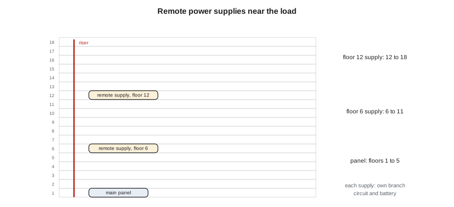
At Riverlight Tower, the 18-storey apartment building that Bramwell maintains, Gerry takes Sasha into the fire alarm control room on the ground floor and opens the panel's back box. 'This is where the building's power becomes fire alarm power,' he says. The panel's power supply takes 120 volts AC from a red-labelled breaker in the emergency electrical panel, converts it to regulated 24 volts DC, runs the panel's electronics and notification circuits, and keeps the batteries charged. On the 6th and 12th floors, two remote power supplies do the same job for the notification circuits on the upper floors. This lesson covers how fire alarm power supplies work, how they are rated and loaded, and the rules for the branch circuits that feed them.
The primary power source
A fire alarm system's primary power comes from the building's electrical system, through a dedicated branch circuit that serves nothing else. The circuit's breaker or disconnect must be identified as the fire alarm circuit, usually with a red marking, and it is locked or otherwise protected so that it can't be switched off by mistake. Its location is recorded at the panel, so that a technician who needs to isolate the panel knows exactly which breaker to open, and so that a responding firefighter can find it.
In Canada, the Canadian Electrical Code Section 32 and CAN/ULC-S524 set the requirements for the fire alarm system's supply: a separate circuit, a disconnecting means coloured red, identified and lockable in the on position, with nothing else connected to it. Where the building has an emergency generator, as Riverlight Tower does, the National Building Code requires the fire alarm system to be on the emergency supply, and the batteries still provide the secondary supply that keeps the system running without a gap while the generator starts.
The branch circuit's ampacity is chosen from the power supply's input rating, which includes the current needed to recharge flat batteries. A typical panel draws only a few hundred milliamps from the line in normal standby, but several amps while it recharges after a long outage. The panel maker's installation manual gives the input current, and the electrician sizes the breaker and conductors to it.
How a fire alarm power supply works
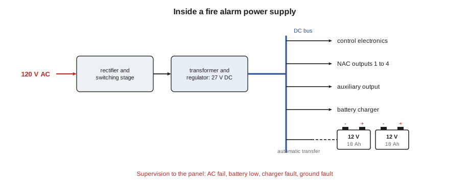
A fire alarm power supply is a switching power supply. It rectifies the incoming AC to DC, switches it at high frequency through a small transformer to reduce the voltage and isolate the output from the line, and regulates the output to a steady DC voltage, commonly about 27 volts, so that it can float-charge a 24-volt lead-acid battery. The supply also contains a battery charger, transfer circuitry that switches the load to the battery instantly when the AC fails, and supervisory circuits that report AC loss, battery trouble, charger failure and ground faults to the panel.
Not every supply produces filtered DC. Some panels and remote power supplies provide full-wave rectified, unfiltered DC to their notification circuits, especially older models. Full-wave rectified power pulses at twice the line frequency, and appliance data sheets give a different current for it, usually higher than for filtered DC, because the appliance draws its energy during the peaks. A technician must use the current for the type of power the panel actually supplies.
Ratings and loading
A power supply has a total output rating, often given in amps at 24 volts, and a rating for each output circuit. A remote power supply rated at 8 amps total might have four notification outputs, each rated 3 amps, so that no single circuit can draw more than 3 amps and the total of all four must not exceed 8. The panel's own internal supply has to run the panel's electronics and its signalling line circuits as well, so the current available for notification and auxiliary loads is less than the supply's full rating. The maker's installation manual gives the limits, and the design must stay within them.
Good design does not load a supply to 100 percent of its rating. Many designers keep notification loads to 80 or 90 percent of each circuit's and each supply's rating, leaving room for the extra current strobes draw at low voltage, for appliances added later, and for ageing. Bramwell's standard is 80 percent of each circuit's rating and 85 percent of the supply's total.
# Loading check for a remote power supply (illustrative ratings)
supply_rating = 8.0           # amps, total of all outputs
circuit_rating = 3.0          # amps, each notification output
circuits = {"NAC 1": 2.31, "NAC 2": 2.64, "NAC 3": 1.92, "NAC 4": 0.0}   # alarm current, amps
aux = 0.35                    # auxiliary load, amps
for name, amps in circuits.items():
    pct = amps / circuit_rating * 100
    print(f"{name}: {amps:.2f} A, {pct:5.1f} % of rating {'over 80 %' if pct > 80 else ''}")
total = sum(circuits.values()) + aux
print(f"total {total:.2f} A, {total / supply_rating * 100:.1f} % of the supply's rating")NAC 1: 2.31 A, 77.0 % of rating NAC 2: 2.64 A, 88.0 % of rating over 80 % NAC 3: 1.92 A, 64.0 % of rating NAC 4: 0.00 A, 0.0 % of rating total 7.22 A, 90.2 % of the supply's rating
In this example, NAC 2 is at 88 percent of its rating, over Bramwell's 80 percent limit, so one or two of its appliances would be moved to the unused NAC 4.
Remote power supplies and notification extender panels
In a large building, running every notification circuit from the main panel would mean very long circuits with large voltage drops. Remote power supplies, also called notification extender panels or booster supplies, solve this by putting the power near the load. Each is fed from its own dedicated branch circuit, has its own battery, and is triggered by the main panel through a control circuit or an addressable module. It then powers its own notification circuits with its own supply. The main panel supervises the remote supply for troubles, and the remote supply supervises its own circuits.
Remote supplies must be compatible with the appliances and the synchronization method. Strobes on the same floor, or in the same field of view, must flash in synchrony, so a remote supply's outputs have to be synchronized with the main panel's and with each other. The maker's compatibility list says which supplies, sync modules and appliances can be combined.
Auxiliary power
Panels and remote supplies have auxiliary outputs for devices that need continuous power: annunciators, duct detector modules, relays, door holders and four-wire smoke detectors. Some auxiliary outputs are 'resettable', switching off briefly when the panel is reset so that latching devices such as four-wire detectors reset; others are continuous. Some are designed to drop out in alarm, for door holders that must release. The current on auxiliary outputs counts against the supply's rating and against the battery, both in standby and in alarm, and auxiliary loads added after the original design are a common reason for batteries running short.
Door holders are a good example of how auxiliary loads affect the battery. A magnetic door holder draws current continuously to hold the door open, and a building with forty holders can draw an amp or more on standby. Many designs power door holders from a separate, non-battery-backed source or from a circuit that drops on AC failure, so that the doors close when the power fails and don't drain the fire alarm battery; the code and the door hardware rules decide which is allowed.
Ground fault detection
Fire alarm power supplies are not grounded on their DC side. Instead, they monitor the DC conductors for any connection to ground and report a ground fault trouble when one occurs. This is why a single accidental connection between a field conductor and a metal box, a conduit or a building's steel doesn't cause a short or blow a fuse: it causes a trouble, which tells the technician to find and fix the fault before a second fault on another conductor creates a real short or a false alarm. Lesson 10 covers ground faults in detail.
AC power measurements
When a technician measures a panel's primary supply, the AC voltage should be within the range the maker specifies, typically 120 volts plus or minus about 10 to 15 percent. A low or fluctuating AC voltage can cause the panel to report AC trouble repeatedly, especially under the load of recharging batteries. Measuring at the panel's terminals with the charger running shows the voltage the supply actually sees. AC current is measured with a clamp meter on one conductor, not both, because the currents in the two conductors cancel.
Worked problem
A new fit-out at Tamarind House
A tenant fit-out on the fourth floor of Tamarind House adds eight horn-strobes at 75 cd, each drawing 0.264 A, to NAC 3 of the panel. The panel's NAC outputs are rated 2.5 A each and its total notification capacity is 6 A. NAC 3 already carries 0.92 A, and the panel's other notification circuits carry 3.1 A together. Does the addition fit?
Show solution
- The new appliances add 8 × 0.264 = 2.11 A.
- NAC 3 would carry 0.92 + 2.11 = 3.03 A, over its 2.5 A rating.
- The panel's total would be 3.1 + 3.03 = 6.13 A, over its 6 A capacity.
- The addition does not fit as designed.
Answer: Ravi redesigns the fit-out with a remote power supply on the fourth floor. It is fed from a new dedicated branch circuit, triggered by an addressable control module, and has two circuits of its own. The panel's battery calculation is redone without the new strobes, and a separate calculation is made for the new supply.
When the primary supply misbehaves
Many trouble calls turn out to be primary power problems rather than fire alarm faults. A panel that reports AC failure every evening at the same time may share a neutral with a large load that switches on then, or its breaker may be tripping on a loose connection that heats under the charger's load. A panel in an older building may report AC trouble during heavy rain because its branch circuit passes through a damp junction box. In each case the fire alarm technician's job is to measure, identify the cause and report it to the building's electrician, because the branch circuit belongs to the building's electrical system, not to the fire alarm contractor.
AC power failure is reported at the panel and usually transmitted to the monitoring station after a delay, so that brief flickers don't send a signal. The delay is set by the panel's programming and by the standard. A technician who switches off a panel's breaker to work on it should expect the AC trouble to reach the monitoring station unless the account is on test, and should record the time the AC was off, because the batteries will need time to recharge afterwards.
After any long power failure, the batteries are recharging, and the charger is drawing its maximum current from the branch circuit. If the power fails again before the batteries are fully recharged, the system has less than its full secondary capacity. This is one reason standards require chargers to recharge batteries within a limited time, and why technicians check the batteries after a building has had a long outage.
Lastly, the primary supply's breaker and the panel's power supply are part of the system's record: the panel's documentation lists the electrical panel and circuit that feed it, and every remote supply has the same information posted inside its cabinet. During the annual inspection, the technician confirms that the information is still correct, because electrical panels are relabelled and circuits moved during renovations, and a wrong record can send a firefighter or a technician to the wrong breaker.
Common mistakes
MistakeLeaving a panel's breaker unlabelled or unlocked.
InsteadMark it in red, identify it and lock it on.
MistakeUsing the filtered-DC appliance current on a panel with full-wave rectified outputs.
InsteadUse the current for the type of power supplied.
MistakeLoading notification circuits to 100 percent of their rating.
InsteadLeave margin for low-voltage current rise and future additions.
MistakeAdding auxiliary loads without revising the battery calculation.
InsteadEvery auxiliary load counts against the battery.
MistakeMeasuring AC current with the clamp around both conductors.
InsteadClamp one conductor; the two currents cancel.
Summary and key terms
- Primary power comes from a dedicated, identified, locked branch circuit.
- Fire alarm power supplies regulate about 27 V DC and float-charge the batteries.
- Each supply and each output has a rating; good design leaves a margin.
- Remote power supplies put power near the load in large buildings.
- Auxiliary loads such as door holders count against the supply and battery.
- The DC side is monitored for ground faults rather than grounded.
- Primary power source
- The normal supply to the fire alarm system from the building.
- Remote power supply
- A separately fed and battery-backed supply that powers notification circuits near their loads.
- Full-wave rectified
- Unfiltered DC that pulses at twice the line frequency.
- Auxiliary output
- A power output for annunciators, relays, holders and other devices.
- Float charge
- A steady charging voltage that keeps a battery full without overcharging it.
- Ground fault
- An unintended connection between a circuit conductor and ground.
Practice problems
Work each problem on paper first, then reveal the answer to check.
A notification output is rated 3 A. What is 80 percent of its rating?
Show answer
2.4 A.
A supply rated 6 A carries 4.9 A in alarm. What percentage is that?
Show answer
About 82 percent.
Why is a fire alarm panel's breaker locked on?
Show answer
So that nobody switches off the system's primary power by mistake.
What does a remote power supply need besides its own battery?
Show answer
Its own dedicated branch circuit and a trigger and supervision connection to the panel.
Why might door holders be powered from a supply without battery backup?
Show answer
So that the doors close on power failure and don't drain the fire alarm battery.
Lesson quiz · 5 questions
Score 60% or more to complete this lesson.
Create a free account to save your progress, take quizzes and earn a certificate.